89Condair CHD, CHD-S and CHD-NA
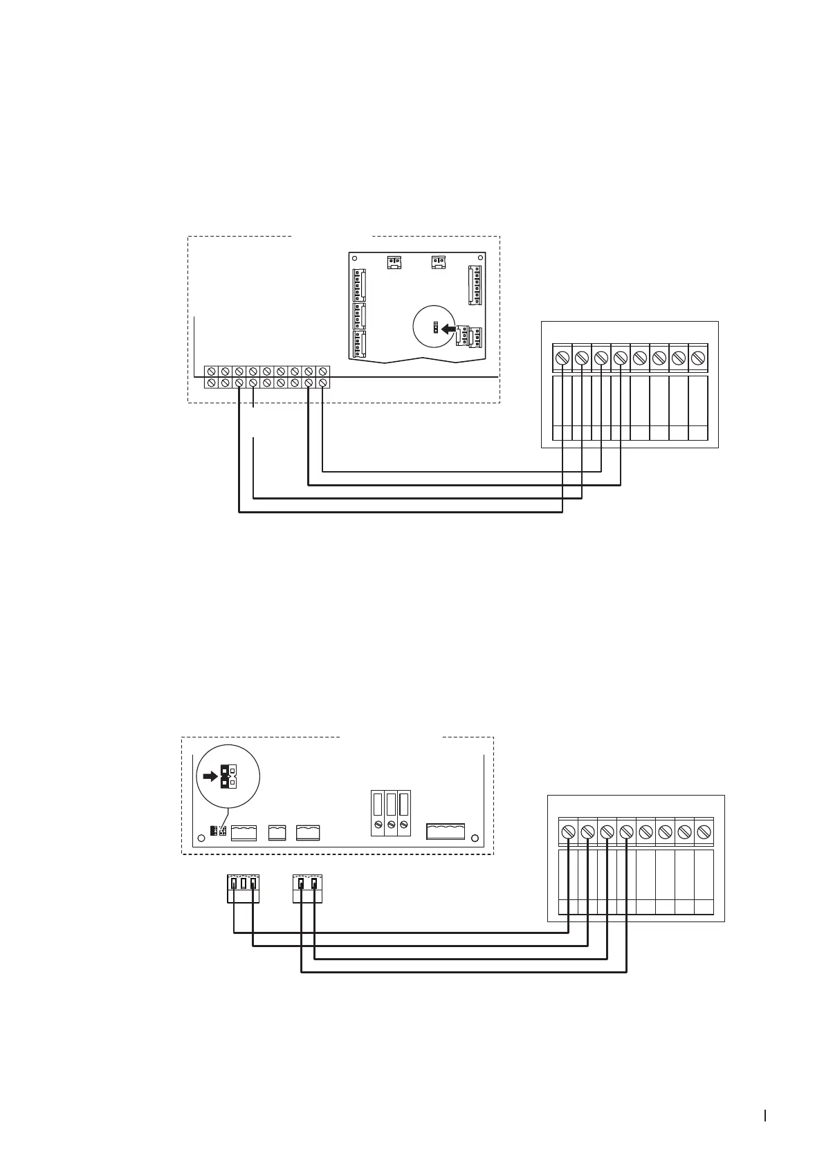
6.7.3 Connecting the CHD or CHD-NA to the Condair GS
1. Connect the Condair CHD or CHD-NA to the corresponding terminals of the terminal block of the
Condair GS according to the wiring diagram below.
Note: The voltage supply of the CHD or CHD-NA is established via the terminals "+24 VDC" and
"GND" of the terminal block or via an external 24 V AC/DC voltage supply.
2. On the driver board of the Condair GS: set a Jumper on JP4-24V.
CHD / CHD-NA
0V / GND
1
24V AC/DC
2
DO1
3
DO1
4
DO2
5
DO2
6
RT
7
RT
8
24 VDC
1
2
3
4
5
67
89
24VAC
Safety Loop
GND
GND
FTBD
CH1
CH2
+24 VDC
Condair GS
J1
J10
J3
J7
J8
J1
J2
JP2
24V 10V
Driver board
Condair GS
6.7.4 Connecting the CHD or CHD-NA to the Condair CP3mini
1. Connect the Condair CHD or CHD-NA to the corresponding terminals on the power board of the
Condair CP3mini according to the wiring diagram below.
Note: The voltage supply of the CHD or CHD-NA is established via the terminals "V+" and "GND"
of terminal block "X1" or via an external 24 V AC/DC voltage supply.
2. On the power board of the Condair CP3mini: set a Jumper on JP2-24 V and remove the Jumper on
JP1-5V (if a jumper is set).
CONT.SIGN
V+
GND CTRL
X1 X4 X6
CTRL V+
1 21 21 2 3
GND
BASIC
0-10V
On/Off
24V
5V
PRO
JP4
JP3
JP2
JP1
LIMGND SC1SC2
SAFETY
SC1SC2
24V
5V
JP2
JP1
Condair CP3 mini
PWR
MAIN SUPPLY
X9
L
N PE
X8
N L SW N SWL
CHD / CHD-NA
0V / GND
1
24V AC/DC
2
DO1
3
DO1
4
DO2
5
DO2
6
RT
7
RT
8
Power board Condair CP3mini