90 Condair CHD, CHD-S and CHD-NA
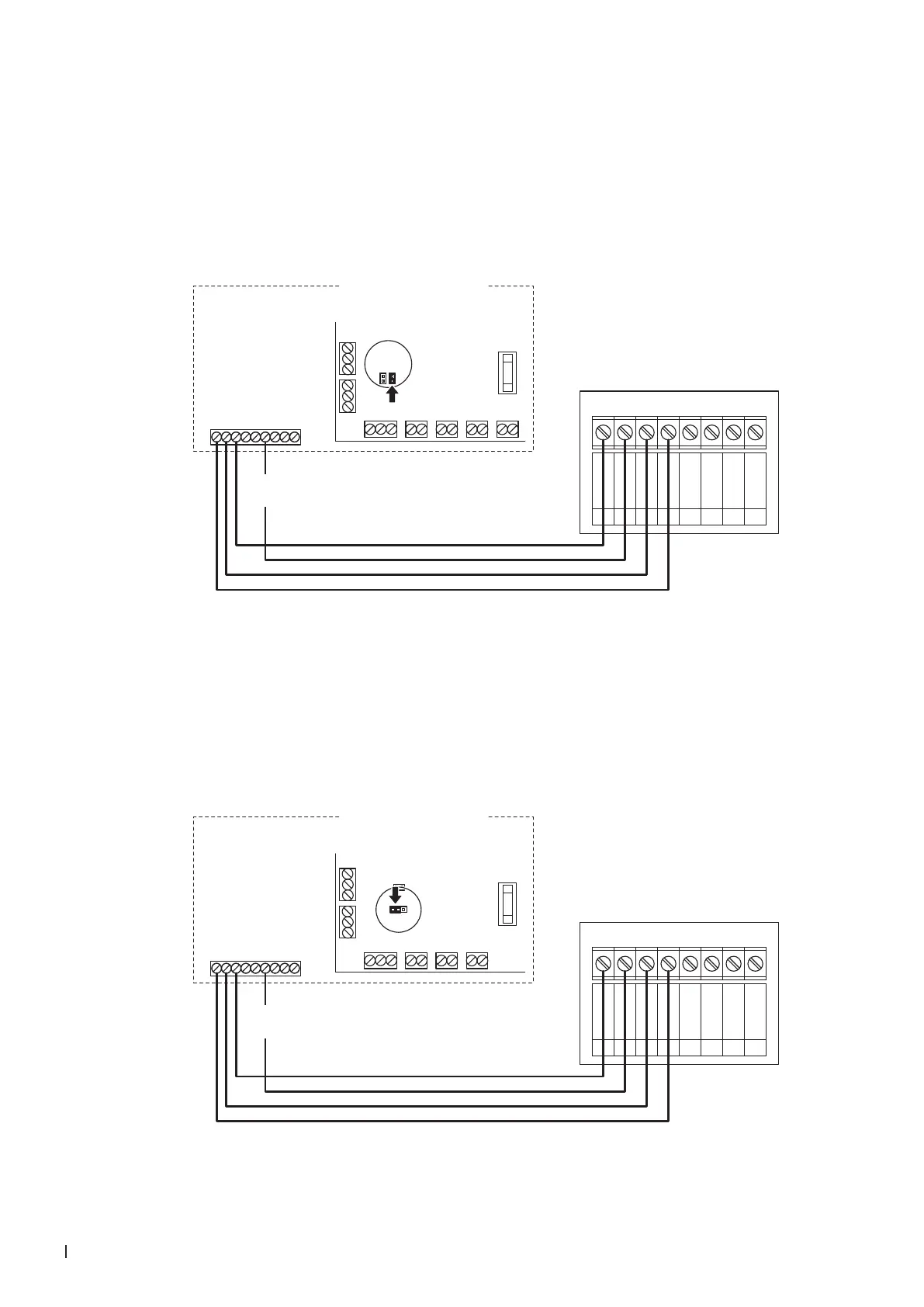
6.7.5 Connecting the CHD-NA to the Condair RS/RS OC (NA)
1. Connect the Condair CHD-NA to the corresponding terminals on the driver board of the Condair RS/
RS OC according to the wiring diagram below.
Note: The voltage supply of the CHD-NA is established via the terminals "V+" and "GND" of terminal
block "XE2" or via an external 24 V AC/DC voltage supply.
2. On the driver board of the Condair RS/RS OC: set a Jumper on JP2 (24 V) and remove the Jumper
on JP1 (10V) (if a jumper is set).
Condair RS/RS OC (NA)
BLOWERLIMIT ENABLECONTROL
V+
X8
X9
X12
X11
INGND IN GND 24V IN24V IN
RS485-1 RS485-2
GND D–D+ GND D–D+
24VAC
External Safety Loop
Control signal (GND)
Control signal (IN)
Limit signal (IN)
Control signal (V+)
Limit signal (GND)
Safety circuit BP
Safety circuit BP
1 2 3 4 5 6 7 8 9
XE2
24VDC
X10
24V GND
JP2 (24V)
JP1 (10V)
CHD-NA
0V / GND
1
24V AC/DC
2
DO1
3
DO1
4
DO2
5
DO2
6
RT
7
RT
8
24 VDC
Driver board
Condair RS
Module A
6.7.6 Connecting the CHD-NA to the Condair EL/EL OC (NA)
1. Connect the Condair CHD-NA to the corresponding terminals on the driver board of the Condair EL/
EL OC according to the wiring diagram below.
Note: The voltage supply of the CHD-NA is established via the terminals "24VDC/10VDC" and "GND"
of terminal block "XE2" or via an external 24 V AC/DC voltage supply.
2. Set a jumper on JP1-24V on the driver board of the Condair EL/EL OC.
Condair EL/EL OC (NA)
BLOWERLIM. SIGN. ON/OFFCONT. SIGN.
V+
X8
X9
X12
X11
IN GND IN GND 24V IN24V IN
RS485-1 RS485-2
24V 10V
JP1
JP3
GND D–D+ GND D–D+
24VAC
Sec. Loop
GND
CH1
CH2
24VDC/10VDC
GND
BP Sec. Loop
BP Sec. Loop
1 2 3 4 5 6 7 8 9
XE2
CHD-NA
0V / GND
1
24V AC/DC
2
DO1
3
DO1
4
DO2
5
DO2
6
RT
7
RT
8
24 VDC
Driver board
Condair EL
Module A