5. Each Component Function
User’s Manual
69
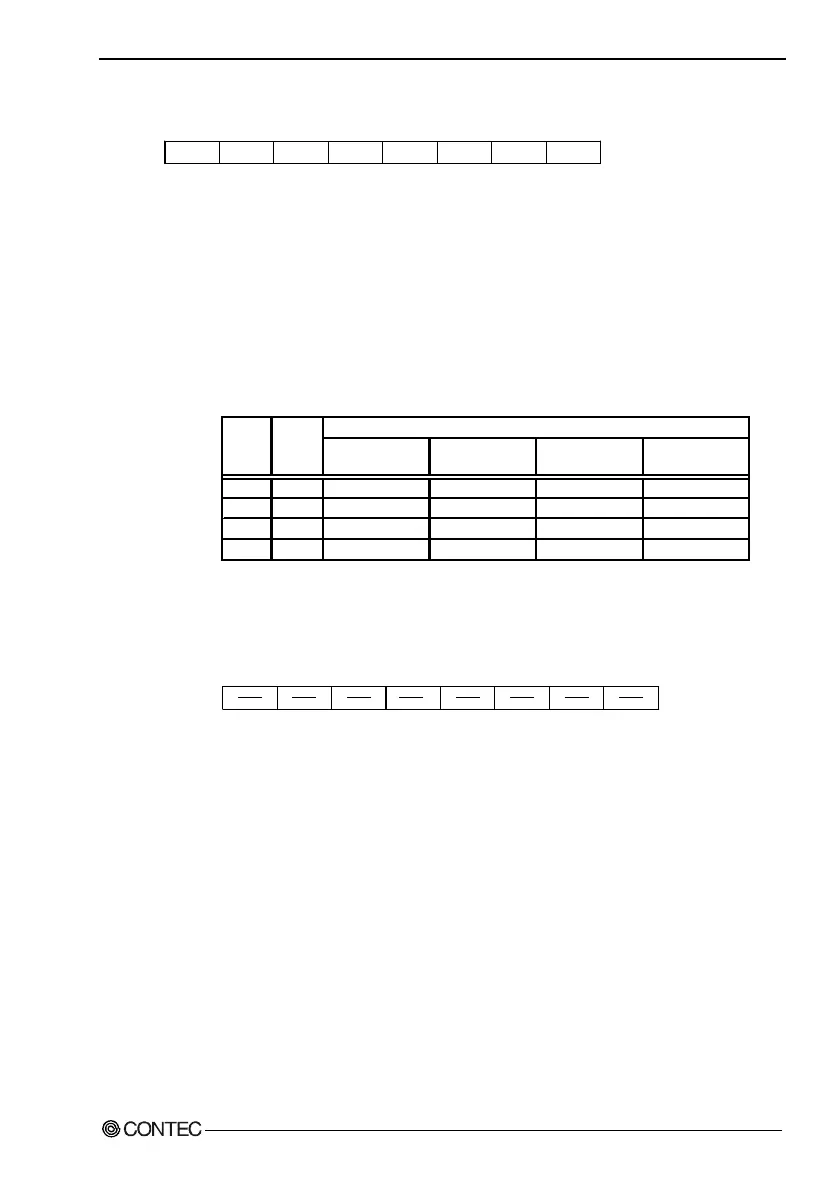
* 4001h (bit4-6): Alarm out output control
--- WD_S0 R/W (Default: X0XX0000b)WD_S1 PO2_M PIM2 PIM1 PIM0RESET
D6 D5 D4 D3 D2 D1 D0D7
Figure 5.9. Alarm Out Output Control Port (4001h)
PO2_M : PO2/WDT pin output setting
0 : Set the RAS connector's PO2/WDT(12) signal to PO2
(general-purpose output).
1 : Set the RAS connector's PO2/WDT(12) signal to
alarm out.
Table 5.20. WD_S1 and WD_S0: Alarm-out Output Status
Settings
When power is
turned off
When BIOS
starts *1
When
WDT starts
When time
expires on WDT
0 0 OFF OFF OFF ON
1 0 OFF OFF ON OFF
1 1 OFF ON ON OFF
0 1 OFF ON OFF ON
*1: For information on the external alarm output setting at BIOS startup, see Chapter 4,
BIOS Setup.
External alarm output status
WD_S0WD_S1
* 4002h: WDT control
R/W
D6 D5 D4 D3 D2 D1 D0D7
Figure 5.10. WDT Control Port (4002h)
R : Cancels WDT stop/alarm.
Read data is undefined.
W : Start and clear the WDT
Write A5h to start and clear the WDT.