5. Each Component Function
68 User’s Manual
* 0071h: Counter clock setting 2 (clock control register)
Set clock frequency in register A and control output with register B.
R/W (default: 00100110b)
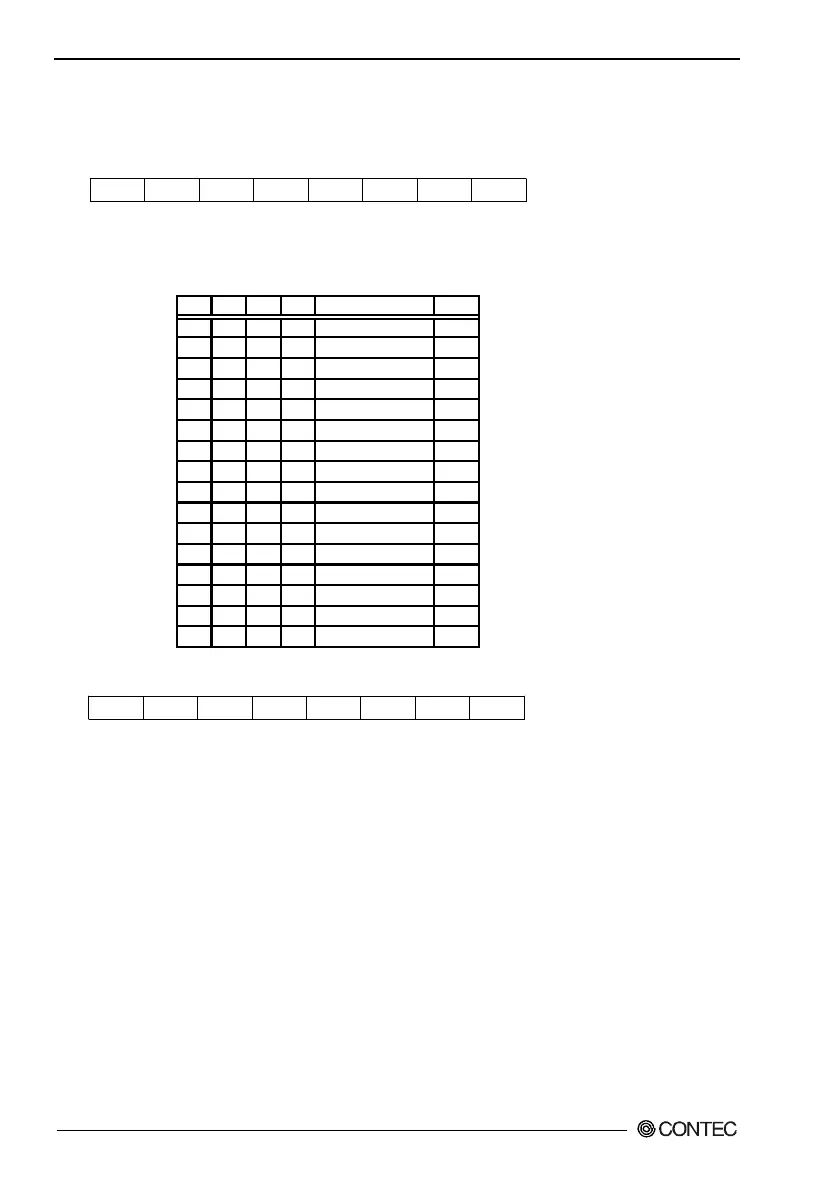
RS3 RS2 RS1 RS0rsv rsv rsv rsv
Figure 5.7. Register A: Counter Clock Frequency Setting
Table 5.19. Counter Clock Frequency Settings
RS3 RS2 RS1 RS0 Counter clock Unit
0 0 0 0 ---
0 0 0 1 7.8125 msec
0 0 1 0 15.625 msec
0 0 1 1 244.14
µ
sec
0 1 0 0 488.282
µ
sec
0 1 0 1 976.562
µ
sec
0 1 1 0 1.958125 msec
0 1 1 1 3.9063 msec
1 0 0 0 7.8125 msec
1 0 0 1 15.625 msec
1 0 1 0 31.25 msec
1 0 1 1 62.5 msec
1 1 0 0 125 msec
1 1 0 1 250 msec
1 1 1 0 500 msec
1 1 1 1 1 sec
rsv
R/W (default: 00000010b)
D6 D5 D4 D3 D2 D1 D0D7
rsv rsv rsv CLKE rsv rsv rsv
Figure 5.8. Register B: Counter Clock Output Control
CLKE: Enable setting for the clock to be input to the counter
1 : Enabled
0 : Disabled
* Do not change the rsv bits since they are used by the system.
After reading the same port, manipulate bits to write data one
more time.