5. Each Component Function
User’s Manual
67
Out 0070h 0Bh : Set the counter clock index register to
register B.
In 0071h : Read register B to view rsv bit status.
Out 0071h 0Ah : Set counter clock output to Enable.
: (Do not change the rsv bit.)
Out 4004h 02h : Set the event at the time of WDT
expiration to IRQ5.
In 4002h : Stop the WDT timer and cancel the
alarm.
Out 4003h 3Ch : Set the WDT expiration time to 15sec.
Out 4002h A5h : Start and clear the WDT.
In 4002h : Stop the WDT and cancel the alarm.
I/O Addresses and Instructions
* 0070h: Counter clock setting 1 (index register)
Select the register to be set at 0071h.
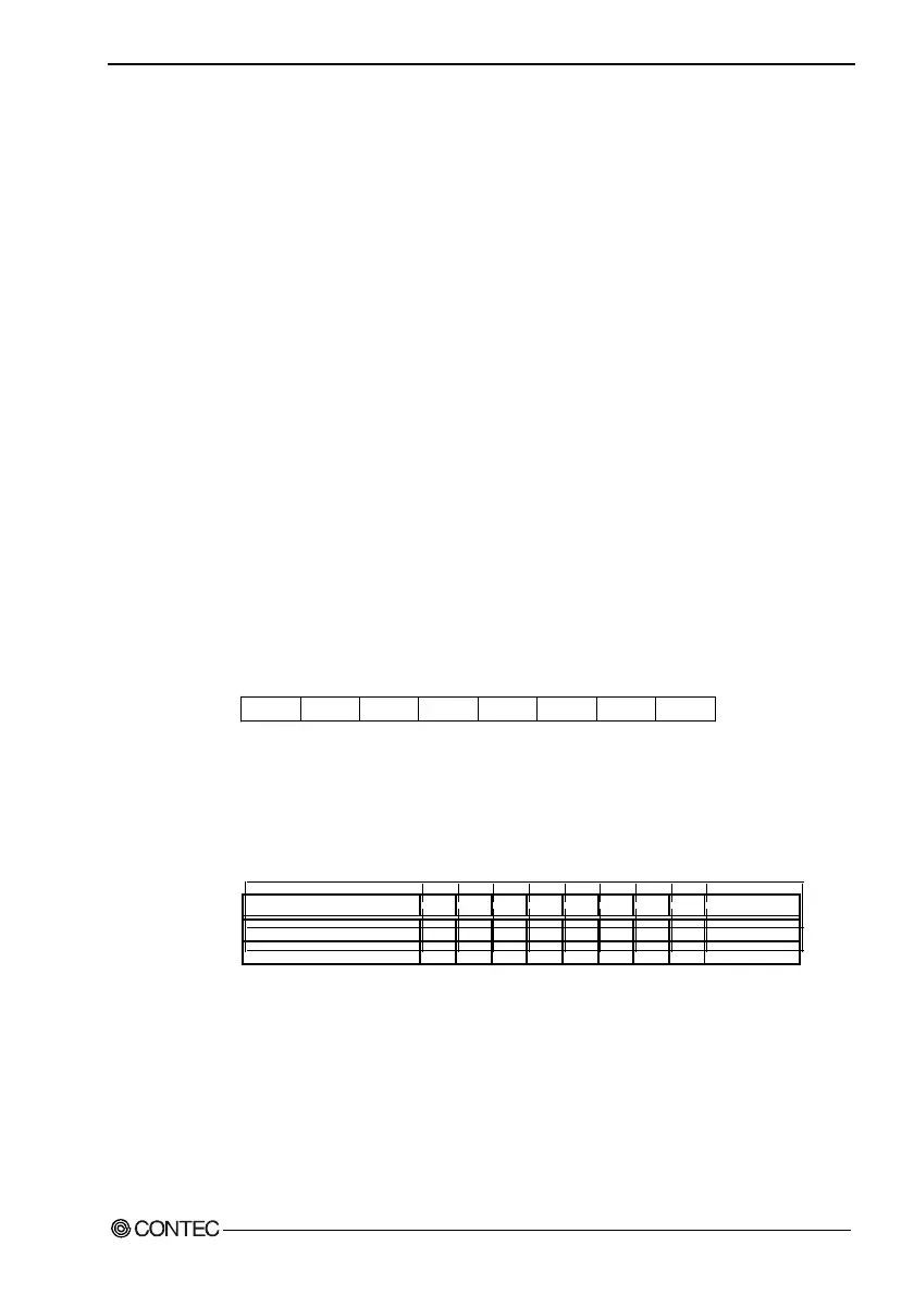
AD7 AD5 R/WAD6 AD4 AD2 AD1 AD0AD3
D6 D5 D4 D3 D2 D1 D0D7
Figure 5.6. Index Register Port
By referring to Table 5.17, output data to 0070h according to the
register you want to set at 0071h.
Table 5.18. Index Register Settings
Register to be set at 0071h AD7 AD6 AD5 AD4 AD3 AD2 AD1 AD0 Data (HEX)
Register A 0 0 0 0 1 0 1 0 0A
Register B 0 0 0 0 1 0 1 1 0B
* Do not set values other than shown above.