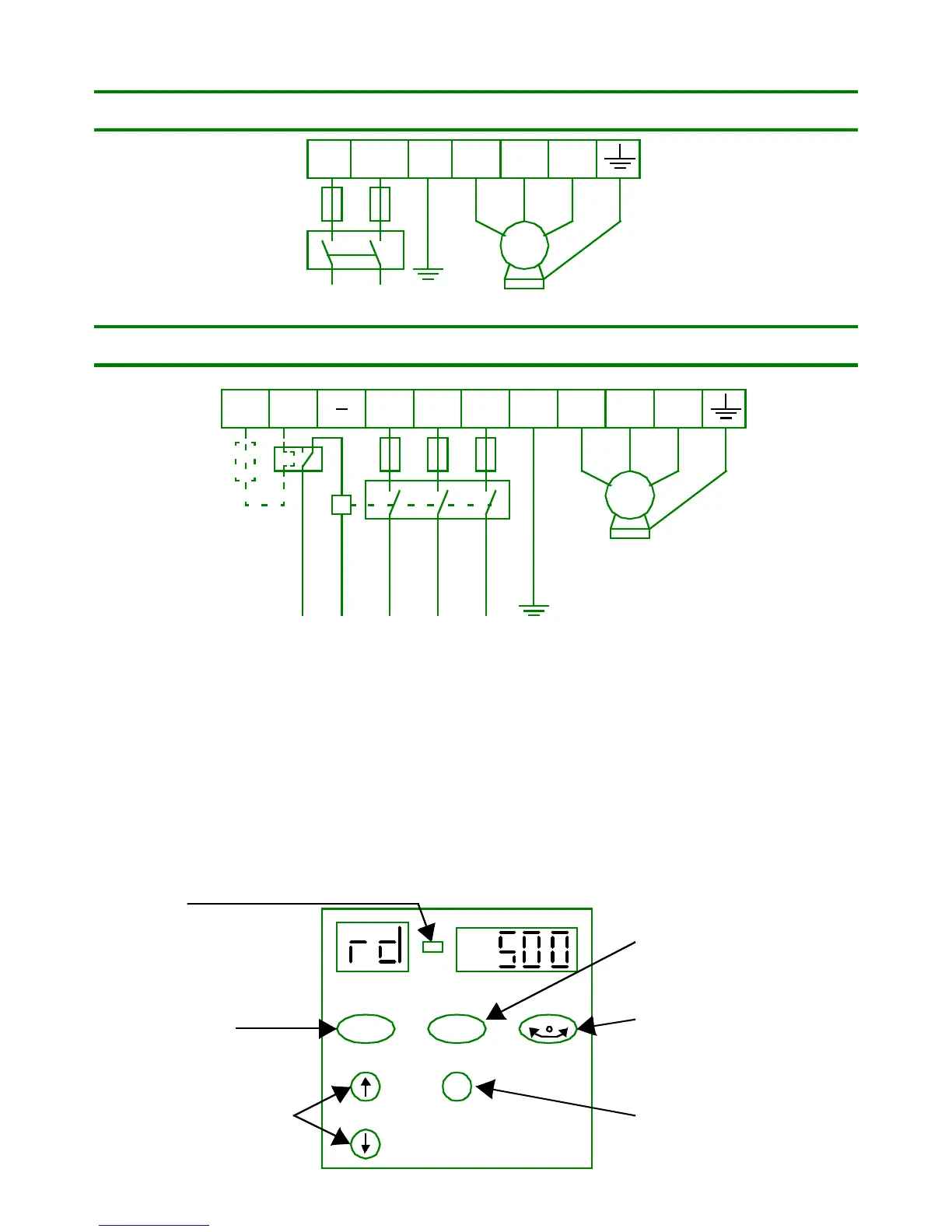
POWER CONNECTIONS
Commander SE size 1
Commander SE sizes 2, 3 & 4
TO OPTIMISE PERFORMANCE, SET MOTOR MAP:
Parameter 6.
Enter motor rated current in amps from motor nameplate.
Parameter 7.
Enter motor rated speed in rpm from motor nameplate.
Parameter 8.
Enter motor rated voltage in volts from motor nameplate.
Parameter 9.
Enter motor power factor from motor nameplate.
DISPLAY AND KEYPAD
M
L1 PE U
V
W
INPUT VOLTAGE
200-240V AC, 1 phase
L2/N
M
L1 L2 U
V
W
INPUT VOLTAGE
200 - 240V AC, 1 phase & 3 phase: 200V AC units
(single phase up to 2.2kW, connect supply to L1 and L2)
380 - 480V AC, 3 phase: 400V AC units only
L3
DBR
+
Optional
Braking
Resistor
PE
gn LED
Increase and decrease keys
Use to select and edit
parameters, also to vary
motor speed in keypad
control.
Run key,
Use to start drive
in keypad mode.
Stop / Reset key,
Use to stop the drive in
keypad mode and to reset
the drive in any mode.
Forward/Reverse key,
Use to reverse motor
direction in keypad mode
when bit parameter 26=On.
Mode key,
Use to change mode
of operation of display.
Parameters are saved each
time the Mode key is pressed
O
M
I
.
2