EasyManua.ls Logo

Control Techniques UD70 User Manual

Control Techniques UD70
154 pages
To Next Page IconTo Next Page
To Previous Page IconTo Previous Page
Page #138 background imageLoading...
Page #138 background image
UD70
Issue code: 70nu2
9-2 Diagnostics
9.2 Run-time trip codes
When the Drive is tripped, the display shows tr followed by a two-digit
number (eg. tr 41). The error number can be determined in an ERROR task
by reading virtual parameter #88.01.
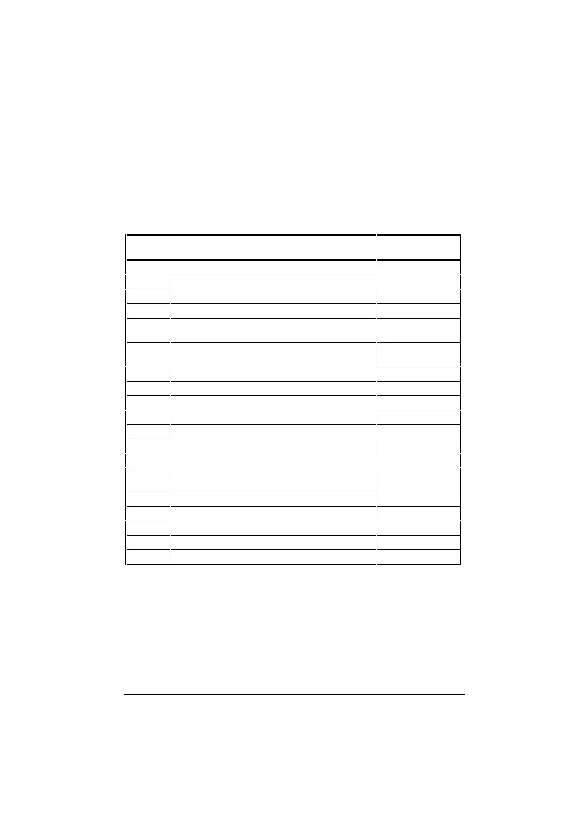
The possible trip codes are as follows:
Error
number
Description Action
40 Unknown error Always trips
41 Parameter does not exist Trips when #17.14 = 1
42 Parameter write failed: parameter is read only Trips when #17.14 = 1
43 Parameter read failed: parameter is write only Trips when #17.14 = 1
44 Parameter write failed: parameter value is over-range Trips when #17.14 = 1
and #17.17 = 1
45 Virtual parameter access failed: IOLINK is not running Trips when #17.14 = 1
and #17.15 = 1
46 ~ 48 Internal error Always trips
49 Wrong system loaded Always trips
50 Maths error in the program, eg. divide by zero, overflow, etc Trips when #17.14 = 1
51 DPL array index is out of range Trips when #17.14 = 1
52 User generated trip from control word Always trips
53 DPL program incompatible Always trips
54 DPL overload – a task has run out of time Trips when #17.14 = 1
55 RS485 trip (mode 3, mode 4, etc) Trips when #17.14 = 1
and #17.15 = 1*
56 Option module and system-file are incompatible Always trips
57 Illegal operating system call Always trips
58 - 59 Internal error Trips when #17.14 = 1
60 - 69 High speed communications option generated trips Trips when #17.14 = 1
Prc2 Watchdog trip (see WDOG command, chapter 7) Trips when #17.18 = 1
(* Trip 55 occurs only when an I/O Box is connected and operating, and
Mode 3 or 4 serial communications fail.)

Table of Contents

Other manuals for Control Techniques UD70

Question and Answer IconNeed help?

Do you have a question about the Control Techniques UD70 and is the answer not in the manual?

Control Techniques UD70 Specifications

General IconGeneral
BrandControl Techniques
ModelUD70
CategoryControl Unit
LanguageEnglish

Summary

Safety Information

General Information

Introduction to UD70 and DPL Toolkit

UD70 Overview and DPL Toolkit Basics

Explains the UD70 as a microcomputer for Unidrive flexibility and the DPL Toolkit for software development.

UD70 Memory and PC Requirements

Details UD70 memory storage and minimum PC specifications for DPL Toolkit.

Technical Data and User Knowledge

Lists UD70 technical specifications and assumes basic Windows knowledge for users.

Installation and Configuration

Installation Procedure

Instructions for physically fitting the UD70 module into the Unidrive.

System Configuration and DPL Toolkit Setup

Details host PC connections (RS232) and installing the DPL Toolkit.

DPL Toolkit Operations

DPL Toolkit Overview and File Management

Introduces the DPL Toolkit's capabilities and file handling procedures.

Editing Programs and Applying Styles

Covers editing code, using styles, and auto-indent features within the DPL Toolkit.

Compiling and Running Programs

Details the process of compiling DPL programs and executing them on the UD70.

Serial Communications

Serial Communications Introduction

Explains serial communication links using RS485 for UD70 systems.

Hardware Connections and ANSI Protocol

Details RS485 hardware connections, ANSI communications fundamentals, and frames.

Serial Modes and ANSI Instructions

Outlines various RS485 modes and available ANSI instructions for communication.

Reference Guide

UD70 Tasks and Programming Structures

Explains different task types (INITIAL, BACKGROUND, CLOCK) and their roles in UD70 programming.

DPL Instructions and Functions Reference

Details various DPL programming instructions and mathematical/signal-processing functions.

UD70 Features

PLC Parameters and Feature Introduction

Introduces PLC parameters and the UD70's advanced position control and profile generation capabilities.

Encoder Lines, Position, and Controller Setup

Explains encoder line units, position calculation, and enabling the position controller.

Default Values and Parameter Descriptions

Details default reset values and provides descriptions for various UD70 parameters.

Logic Diagrams and Digital Lock Control

Illustrates logic diagrams for position control and explains digital lock functions.

Cam Function and Reference Switching

Describes the cam function for slave axis control and switching between control modes.

Timer/Counter Unit and Digital I/O Ports

Details the UD70's timer/counter unit and digital I/O port functionality.

Memory Storage and RS232 Communications

Covers non-volatile memory storage and using the RS232 port for Drive-to-Drive communication.

Diagnostics and Error Handling

Run-time Errors and Trip Codes

Explains run-time errors, their causes, and provides a list of trip codes with their actions.

Compiler Errors and Advanced Error Handling

Lists compiler error messages and details advanced error handling using the ERROR Task.

UD70 Parameters

Set-up Parameters and RS485 Modes

Details UD70 set-up parameters and the various RS485 port modes available.

Virtual Parameters and Control Words

Explains virtual parameters and the function of control and status words.

General-Purpose Parameters and I/O Box Configuration

Lists general-purpose parameters and details I/O box configuration through menus.

Related product manuals