EasyManua.ls Logo

Control Techniques UD70 User Manual

Control Techniques UD70
154 pages
To Next Page IconTo Next Page
To Previous Page IconTo Previous Page
Page #64 background imageLoading...
Page #64 background image
UD70
Issue code: 70nu2
6-4 Serial communications
6.3 ANSI communications
Using the standard ANSI slave protocol
The standard built-in protocol which defines the message structure used to
read and write parameters on the UD70 is ANSI x3.28-2.5-A4. This section
explains this protocol.
The user may also create his own protocol by writing it in a DPL program,
using low-level port commands such as
GETCHAR and PUTCHAR (refer to
Chapter 7 Reference).
ANSI slave protocol is enabled when the RS485-mode set-up parameter is set
at 1 (4-wire) (which is the default setting), or 5 (2-wire). See Serial
communications modes later in this chapter for details of other
communication modes.
Fundamentals of data transmission
Data is transmitted at a fixed speed or baud rate in the form of a character.
A character may typically comprise seven or eight bits.
In order for a receiver to recognize valid data, a frame is placed around each
character. This frame contains a start bit, a stop bit, and an optional parity
bit. Without this frame, the receiver will be unable to synchronize itself
with the transmitted data.
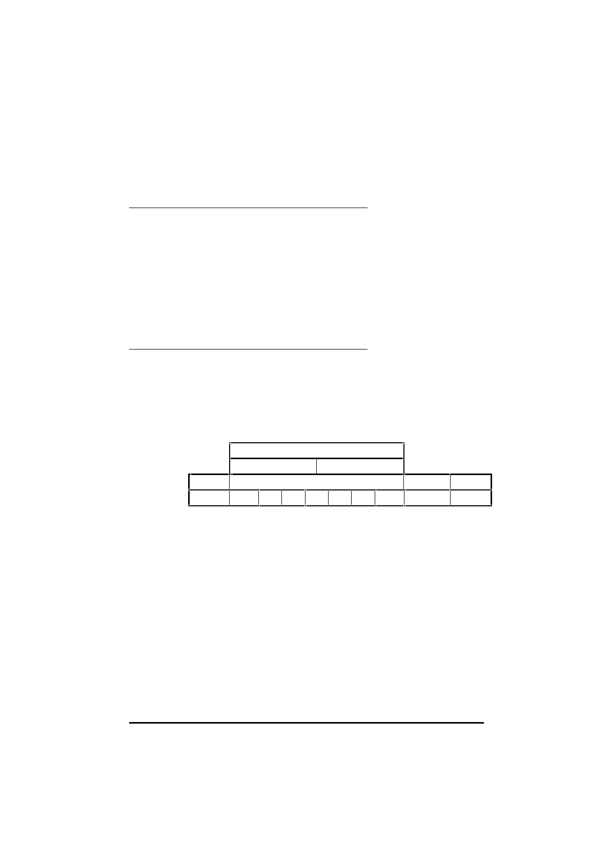
A frame is shown below:
Low ASCII character byte
1st hex character 2nd hex character
Start bit Seven data bits Parity bit Stop bit
0LSB MSB 1
This is known as a 10-bit frame, since there are 10 bits transmitted in total.
The format is often described as follows:
1 start bit, 7 data bits, even/odd/no parity, 1 stop bit.1 start bit, 7 data bits, even/odd/no parity, 1 stop bit.
lsb refers to the least significant bit (ie. bit 0)
msb refers to the most significant bit (bit 6)
The Parity bit is used by the receiver to check the integrity of the data
it has received

Table of Contents

Other manuals for Control Techniques UD70

Question and Answer IconNeed help?

Do you have a question about the Control Techniques UD70 and is the answer not in the manual?

Control Techniques UD70 Specifications

General IconGeneral
BrandControl Techniques
ModelUD70
CategoryControl Unit
LanguageEnglish

Summary

Safety Information

General Information

Introduction to UD70 and DPL Toolkit

UD70 Overview and DPL Toolkit Basics

Explains the UD70 as a microcomputer for Unidrive flexibility and the DPL Toolkit for software development.

UD70 Memory and PC Requirements

Details UD70 memory storage and minimum PC specifications for DPL Toolkit.

Technical Data and User Knowledge

Lists UD70 technical specifications and assumes basic Windows knowledge for users.

Installation and Configuration

Installation Procedure

Instructions for physically fitting the UD70 module into the Unidrive.

System Configuration and DPL Toolkit Setup

Details host PC connections (RS232) and installing the DPL Toolkit.

DPL Toolkit Operations

DPL Toolkit Overview and File Management

Introduces the DPL Toolkit's capabilities and file handling procedures.

Editing Programs and Applying Styles

Covers editing code, using styles, and auto-indent features within the DPL Toolkit.

Compiling and Running Programs

Details the process of compiling DPL programs and executing them on the UD70.

Serial Communications

Serial Communications Introduction

Explains serial communication links using RS485 for UD70 systems.

Hardware Connections and ANSI Protocol

Details RS485 hardware connections, ANSI communications fundamentals, and frames.

Serial Modes and ANSI Instructions

Outlines various RS485 modes and available ANSI instructions for communication.

Reference Guide

UD70 Tasks and Programming Structures

Explains different task types (INITIAL, BACKGROUND, CLOCK) and their roles in UD70 programming.

DPL Instructions and Functions Reference

Details various DPL programming instructions and mathematical/signal-processing functions.

UD70 Features

PLC Parameters and Feature Introduction

Introduces PLC parameters and the UD70's advanced position control and profile generation capabilities.

Encoder Lines, Position, and Controller Setup

Explains encoder line units, position calculation, and enabling the position controller.

Default Values and Parameter Descriptions

Details default reset values and provides descriptions for various UD70 parameters.

Logic Diagrams and Digital Lock Control

Illustrates logic diagrams for position control and explains digital lock functions.

Cam Function and Reference Switching

Describes the cam function for slave axis control and switching between control modes.

Timer/Counter Unit and Digital I/O Ports

Details the UD70's timer/counter unit and digital I/O port functionality.

Memory Storage and RS232 Communications

Covers non-volatile memory storage and using the RS232 port for Drive-to-Drive communication.

Diagnostics and Error Handling

Run-time Errors and Trip Codes

Explains run-time errors, their causes, and provides a list of trip codes with their actions.

Compiler Errors and Advanced Error Handling

Lists compiler error messages and details advanced error handling using the ERROR Task.

UD70 Parameters

Set-up Parameters and RS485 Modes

Details UD70 set-up parameters and the various RS485 port modes available.

Virtual Parameters and Control Words

Explains virtual parameters and the function of control and status words.

General-Purpose Parameters and I/O Box Configuration

Lists general-purpose parameters and details I/O box configuration through menus.

Related product manuals