UD70
Issue code: 70nu2
6-2 Serial communications
6.2 Hardware connections
The following table details the hardware connections for the RS485
communications port.
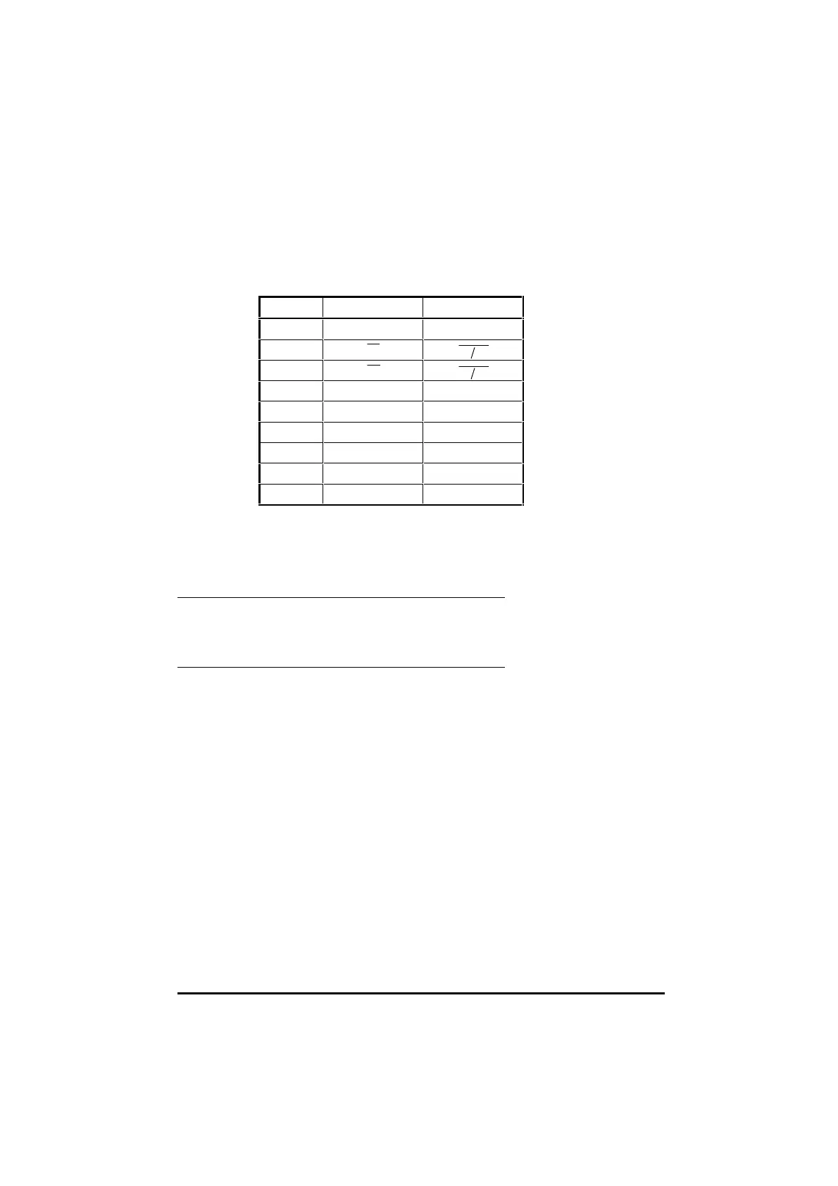
Pin RS485 4-wire RS485 2-wire
1
0V
0V0V
2
Tx
Tx Rx
3
Rx
Tx Rx
4 DI0 *DI0 * DI0 *DI0 *
5 DI1 *DI1 * DI1 *DI1 *
6TxTx Tx/RxTx/Rx
7RxRx Tx/RxTx/Rx
8 DO *DO * DO *DO *
9 0VD *0VD * 0VD *0VD *
* Terminals 4, 5, 8 and 9 form the digital I/O connections of the UD70.
Since they form no part of the serial communications connections they must
not be connected to any serial communications lines, or to the serial
communications 0V (pin 1).
Ground connection
It is recommended that the shield of the data communications cable should
be connected by a low-inductance path to a ‘clean’ ground.
Routing the serial communications cable
A data communications cable should not run parallel to any power cables,
especially ones that connect Drives to motors. If parallel runs are
unavoidable, ensure a minimum spacing of 300mm (1 foot) between the
communications cable and the power cable.
Cables crossing one another at right-angles are unlikely to give trouble.
The maximum cable length for a
RS485 link is 1200 metres (4,000 feet).