UD70
Issue code: 70nu2
8-36 Features
8.13 Digital I/O ports
The UD70 has two digital inputs and one digital output as standard. These
inputs and output are TTL logic (ie. 5V logic), and are made available on the
9-way RS485 port connector, as follows:
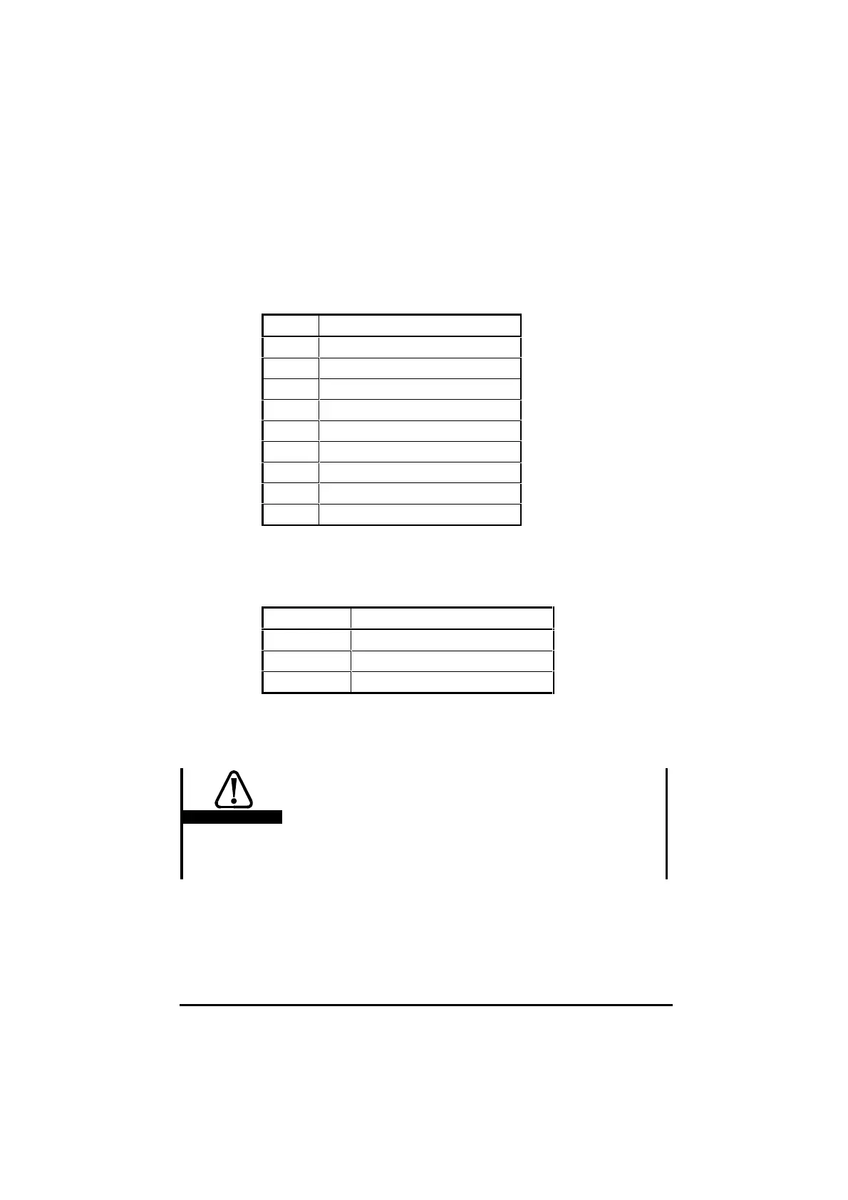
Pin Description
1 RS485 isolated 0V
2RS485 /TX
3RS485 /RX
4 DIGIN0 (TTL digital input 0)
5 DIGIN1 (TTL digital input 1)
6RS485 TX
7 RS485 RX
8 TTL digital output
9Drive 0V
The digital TTL inputs are used in conjunction with the timer/counter unit.
In addition, they are also directly readable by a DPL program.
The digital
TTL output can also be controlled directly from a DPL program.
The following virtual parameters give access to the TTL I/O:
Parameter Function
#86.01 Digital input 0 (DIGIN0)
#86.02 Digital input 1 (DIGIN1)
#86.03 Digital output
The inputs read 00 when at logic high (5V or unconnected), and 11 when at
logic low (0V).
The output is at logic high (5V) when 00 is written.
Warning
The digital output is rated at a maximum of 15 milliamps
(sink/source).
Connections to the digital inputs and outputs should be
kept as short as possible (0.5 metre (20 in) maximum
recommended). External buffering is required if longer
cable lengths are used, or interfacing is needed to
different logic levels.