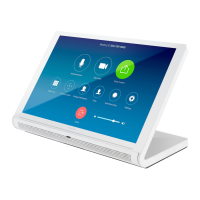
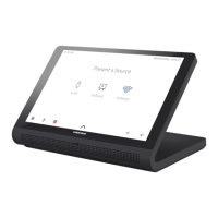
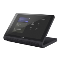
Product Manual — Doc. 7750C TST-902 • 63
6. Once drywall is installed over the mounting bracket, use a standard drywall saw to cut the
drywall along the inside edge of the front of the mounting bracket. The labels on the front
of the mounting bracket indicate the perimeter of the drywall cutout. Refer to
TST-902-DSW-PMK Specifications on page 30 for cutout dimensions.
NOTE:The four tapped holes on the front of the mounting bracket must be exposed in
order to accept the TST-902-DSWmounting screws. These holes are located along the
top and bottom of the drywall opening. The notch at the top center of the mounting
bracket must also be exposed to accommodate the TST-902-DSWlocking latch.
7. (Optional)If required by local building codes, use the 6-32x1-1/2in. screws to install the
included cover plate over the mounting bracket. The cover plate should remain attached
until the TST-902-DSWis installed.
 Loading...