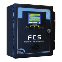
The FCS Flexible Control System is a sophisticated, high-performance controller designed for monitoring and managing various gases in diverse industrial, commercial, and non-hazardous environments. It offers multi-channel configurations for toxic, combustible, and refrigerant gases, as well as industrial applications. The system is designed to accept inputs from digital and/or analog transmitters and/or peripheral devices, communicating via Modbus® RTU RS-485 or 4-20 mA analog input.
Function Description
The FCS Flexible Control System serves as a central control unit for gas detection and environmental monitoring. It is available in 4, 8, 32, and 128 channel models, supporting both Modbus® RTU RS-485 WAN output and BACnet® MS/TP RS-485 WAN output for communication with a Building Automation System (BAS). The system is equipped with four configurable SPDT dry contact relays with field configurable time delays and trigger levels, a full color LCD resistive touch screen with LED panel indicating configurable channel alarm status, relay status and fault conditions, an exclusive USB port for firmware upgrades, data logging, and a door-mounted, audible alarm. The FCS has flexible configuration settings for analog outputs and supports 4-20 mA and Modbus® driven VFDs.
The system's core function is to continuously monitor gas levels from connected transmitters and trigger alarms or control actions based on predefined setpoints. It supports various types of transmitters, including ART Infrared Refrigerant, CGAS-A, CGAS-AP Public Spaces, CGAS-D Digital, CXT Explosion Proof, LPT Low Power, LPT-A Analog, LPT-M Modbus, and LPT-P Digital Car Park. It also integrates with peripheral devices such as LNK-AO Analog Output, LNK-AI Analog Input, LNK-XT Network Extender, RDM Remote Display, RLY-4 Remote Relay, RLY-8 Remote Relay, and RPS-24VDC Remote Power Supply.
Important Technical Specifications
- Gas Type: No internal gas sensors.
- Mechanical:
- Enclosure: ABS / Polycarbonate, rated UL94-HB. Copper coated interior to reduce RF interference. IP54 rating with door mounted, water tight buzzer installed.
- Weight: 1.8 kg / 4 lbs
- Size: 254 mm x 226 mm x 113 mm / 10 in x 8.9 in x 4.44 in
- User Interface:
- Display: 8.1 cm / 3.2 in graphic, 1/4 VGA full color resistive touch LCD display and LED indicators for "POWER", "STATUS 1, 2 and 3", "FAULT".
- Input/Output:
- Inputs: Modbus® RTU RS-485, 4 or 8 internal 4-20 mA analog inputs (Option -AI or -2AI), Peripheral devices on Modbus® RTU RS-485 network.
- Outputs: Modbus® RTU RS-485 or BACnet® MS/TP to BAS, 4 or 8 internal 4-20 mA analog outputs (Option -AO or -2AO), Remote and Peripheral devices on a Modbus® RTU RS-485 network, 2 drive outputs for strobe/horn (0.5 Amp @ 24 VDC).
- Relays (internal): 4 internal SPDT dry contact relays, rated 5A @ 240 VAC.
- Audible Alarm: Standard door mounted buzzer, rated 90 dB @ 30 cm (1 ft), Optional door mounted water tight buzzer (Option -WA), rated 85 dB @ 60.96 cm / 2 ft.
- Top Mounted Strobe: 24 V, 114 mm H x 76 mm dia / 4.5 in H x 3 in diameter (Option -L).
- Electrical:
- Power Requirement: 90 - 240 VAC, 50 - 60 Hz, 75 W Line Voltage.
- Current Draw: Line Voltage (110 VAC) Approximately 1.0 Amp, Line Voltage (220 VAC) Approximately 0.5 Amp.
- Power Distribution: Total power available to Remote and Peripheral Devices and Options 65 W @ 24 VDC.
- Wiring: VAC (line voltage) three-conductor (Line, Neutral, Ground) shielded minimum 18 AWG stranded within conduit. LAN Modbus® RTU RS-485 4-conductor, 16 AWG, stranded shielded. WAN (output to BAS): 4-conductor, 16 AWG, stranded shielded Modbus® RTU (version 1 1b3) RS-485 or BACnet® MS/TP (version 1 rev 14) RS-485.
- LAN / WAN Communication:
- LAN Baud rate: 19,200 (default, configurable)
- WAN Baud rate: 19,200 (default, configurable)
- WAN Modbus ID: 100 (factory default)
- Data bits: 8
- Stop bits: 1
- Parity: none
- BACnet® MS/TP Baud rate: 76,800 (default, configurable)
- Base Address: 270 (factory default)
- MAC Address: 100 (factory default)
- Instance ID: 270100 (the Base Address x 1000 + the MAC Address)
- Data Bits: 8
- Stop Bits: 1
- Parity: none
- Fuses: Automatic resetting thermal.
- Environmental:
- Operating Temperature: -20°C to 40°C (-4°F to 104°F)
- Operating Humidity: 15 - 90% RH non-condensing.
- Certification: CSA-C22.2 No. 205-12, UL508 (Edition 17):2007, EMC: Directive 2004/108/EC and 507/03/006, Type 1, EN61010.
Usage Features
- User-Friendly Interface: The 1/4 VGA full color resistive touch LCD display allows for intuitive navigation through menus and settings.
- Passcode Protection: Access to various menus and settings is protected by passcodes, ensuring secure operation.
- Channel Status Display: The home screen displays the status of all channels, indicating OK, Low-Alarm, Mid-Alarm, Hi-Alarm, and Fault conditions with corresponding color codes (Green, Yellow, Orange, Red).
- Relay Status Bar: Provides a visual overview of the status of all relays, including Active, Silenced, On Delay, Off Delay, Alarm, and Latched conditions.
- Peripherals Status Bar: Displays the status of all main and peripheral LNK-AO devices or Modbus® VFDs.
- Scrolling Display: The channel view of the home screen allows scrolling through channel status bars for each channel.
- Power Up and Warm-up: The system undergoes an initializing start-up sequence with a 2-minute countdown. During this time, the gas alarms are dependent upon the length of time since the unit was last powered up, and the state of the environment is installed.
- Silencing Audible Alarm: The audible alarm can be silenced for a preconfigured amount of time.
- Test Menu Functions: Includes options to test the audible alarm (buzzer), strobe, relays, and analog output.
- Recalibrating Display: Allows for recalibration of the display to improve response.
- Factory Default Settings: Provides configurable settings for door mounted buzzer, alarm level, silence interval, strobe, data logger, relays, alarm setpoints, LAN Modbus® baud rate, WAN Modbus® baud rate, Modbus ID, BACnet® settings, analog input/output calibration, STEL/TWA display, and global alarm.
- Set Clock: Allows setting the correct date and time for the system.
- Data Logging: Includes internal logging memory that stores one year's worth of readings (when set at a rate of logging once per minute). Data is saved in a .csv format and can be extracted via a standard USB connection.
- RDM Remote Display Configuration: The FCS can communicate with RDM Remote Displays, which provide viewing of gas readings, channel status, and faults. It supports various display modes like Line Scroll, Page Scroll, High Channels, Selected Page, and Selected Line.
- Enable/Disable Channels: Individual channels can be enabled or disabled.
- Enable/Disable Relays, Audible, Horns and Strobes: Allows for enabling or disabling specific relays, audible alarms, horns, and strobes.
- Top Mounted Strobe (Option -L): High-powered, red LED flashing beacon for visual alarm indication.
- Manual Shutoff Switch (Option -SW): An optional emergency stop, push button switch that is factory installed on the side of the FCS enclosure, allowing for manual shutdown of equipment in the event of a gas leak.
- Enclosure Door Lock and Keys (Option -DL): An optional door lock for enhanced security.
- Metal Protective Guard (p/n: SCS-8000-SPG): A heavy-duty metal guard to protect against damage, theft, or vandalism.
Maintenance Features
- No Assembly or Virtually No Maintenance: The FCS is designed for minimal maintenance, requiring only occasional cleaning of the enclosure and physically damaging the circuit board or internal components.
- Troubleshooting: The manual provides guidance for troubleshooting common issues such as power problems, numeric keypad malfunctions, and communication issues with transmitters or RDM Remote Displays.
- Firmware Upgrades: The USB port allows for easy firmware upgrades.
- Data Backup: Data logging allows for saving and extracting data, which can be used for analysis and record-keeping.
- Warranty Policy: Critical Environment Technologies Canada Inc. warrants products for a period of two years from the date of purchase. The warranty covers defects in materials and workmanship.
- Service Policy: Critical Environment Technologies Canada Inc. distributors/agents may offer service and repairs. Repairs are warranted for 90 days after date of shipment.
- RMA Process: For returns, a Returned Merchandise Authorization (RMA) number is required.
- Technical Support: Contact information for Critical Environment Technologies Canada Inc. is provided for technical support.