© 2021 All rights reserved. Data subject to change without notice. 33
Rev. C | 2021.12 FCS - Installation Manual
The relays are rated 5 amps @ 240 VAC each and can be used to control remote alarms,
strobes, exhaust fan starters, make up air fan contactors, or signaling other equipment like
re panels or alarm systems, etc.
Maximum number of RLY-4 and RLY-8 remote relay devices by FCS model:
FCS-4 FCS-8 FCS-32 FCS 128
RLY-4
1 max 2 max (no RLY-8) Total # of available relays (internal +
remote) plus strobe/horn drives is 64.
Max number of RLY-4 and/or RLY-8
varies depending on number of strobe/
horn drives used and internal relays
used.
RLY-8
0 1 max (no RLY-4)
NOTE: The remote relays are in addition to the four internal relays that come standard with
each FCS model.
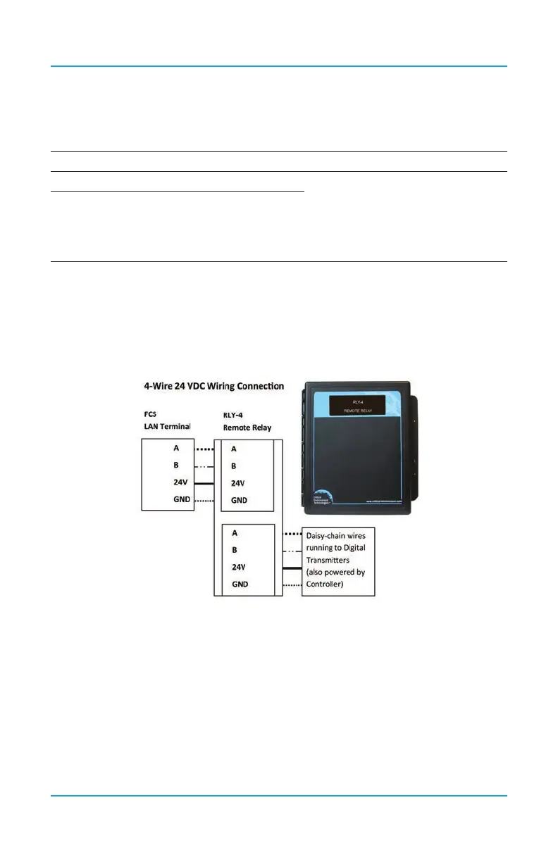
One or more Remote Relay devices can be wired directly to the FCS, followed by digital
transmitters connected in a daisy-chain conguration or they can be wired anywhere along
the digital network in a daisy-chain conguration as required. A goes to A; B goes to B; GND
goes to GND; 24V goes to 24V.
6.19 Wiring RDM Remote Display Connections
The RDM Remote Display is a device that is designed to communicate with the FCS
using Modbus® communication protocol. It displays the real time gas readings from the
FCS and is intended to be mounted and viewed from a remote, relevant location such
as a refrigeration (or other) application where there are two entrances to the room being
monitored. It will provide visual conrmation of the gas level readings inside the room
prior to entry. Simple congurations such as adjusting the display contrast and setting the
Modbus® ID and baud rate can be done in the eld. Other congurations can be set through
the FCS menus. For more information, refer to the FCS Operation Manual.