34 © 2021 All rights reserved. Data subject to change without notice.
FCS - Installation Manual Rev. C | 2021.12
Once the RDM Remote Display is wired to the FCS, the controller needs to be told that the
RDM exists as a remote device. This is done at the controller. Refer to the FCS Operation
Manual for instructions.
Similarly, in order for the controller to communicate with the RDM, the two devices must have
the same baud rate. The factory default baud rate for all CETCI Modbus® devices is 19,200.
If you need to change the baud rate, refer to the RDM Operation Manual for instructions.
The read and write default RDM Modbus® ID is 230. The RDM will automatically broadcast
the display information to Modbus® ID 253. This is the common Modbus® ID for all RDMs
on the network and is used to listen for broadcasts from the controller and receive screen
updates from the controller.
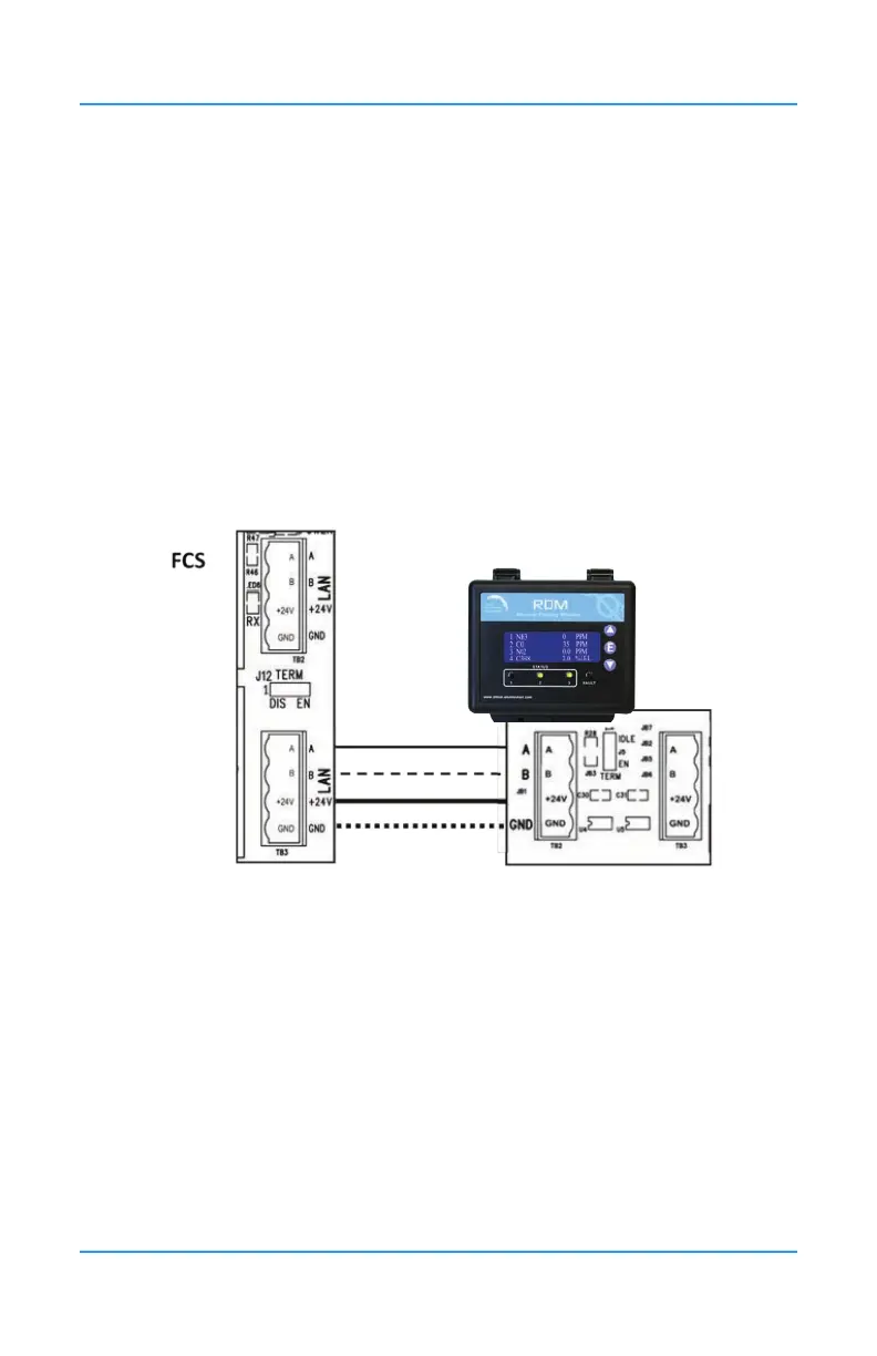
24VDC power is supplied to the RDM from the FCS. Four-conductor, 16 gauge stranded wire
/ cable must be shielded when connecting the controller to the RDM. It should be connected
in a daisy-chain conguration and can be placed anywhere along the digital network as
required. A goes to A; B goes to B; GND goes to GND; 24V goes to 24V.
For more information on the RDM Remote Display, refer to the RDM Remote Display
Operation Manual and the FCS Operation Manual.