© 2021 All rights reserved. Data subject to change without notice. 31
Rev. C | 2021.12 FCS - Installation Manual
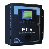
24V - 24 volts DC, not required, no connection on board
GND - ground reference
A and B - RS-485 differential signal pair, A is + and B is -
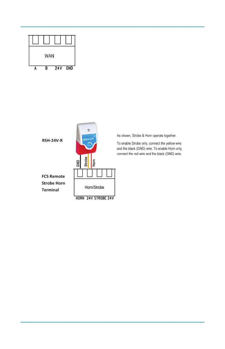
6.16 Wiring Remote Strobe/Horn Using Output Terminal
The FCS provides two output drives of 24 VDC @ 500 mA for connecting up to two remote
horn/strobe devices at the Remote Strobe & Horn Terminal. Refer to Section 5.2 Interior
System Layout (Bottom) for location.
More than two horn/strobe devices can be accommodated by additional relays and power
supplies.
6.17 Wiring Internal Relay Connections
System default is congured such that all relays are “FAIL SAFE” (relay coils are always
energized in non-alarm state). Relays are “common” to channels (activated by multiple alarm
conditions).
The FCS has four SPDT dry contact relays rated MAX 5A at 240 VAC or 30 VDC each. These
relays can be used to control fan starters or coils used for HVAC equipment. The contacts
can also be used for signaling other equipment like re panels or alarm systems. Terminal
blocks are provided to connect to the four MAX 5A / 250 VAC - 30 VDC internal relays.
NOTES:
• The system does not provide any power from these terminals. Dry contacts operate
like a switch to simply activate (switch on) or de-activate (switch off) equipment to be
controlled, such as fan starters.
• System relays are SPDT (single pole, double throw) thereby providing one set of
usable dry contacts. Because the FCS series systems are designed to be fail-safe, the