38 © 2021 All rights reserved. Data subject to change without notice.
FCS - Installation Manual Rev. C | 2021.12
7.3 Power Up and Warm-up
Upon power up, the FCS delays the initializing start-up sequence with a 2 minute countdown
while it waits to make sure there isn’t a power issue with the system. This process reduces
the possibility of corrupting the SD card and the conguration of the FCS if the power is
interrupted during start-up and the device is forced to reboot before initializing.
Most power issues occur and are resolved at the rst system start-up. Power issues may be
caused by events such as:
• Overloaded building mains (for the breaker)
• Incorrectly wiring the FCS LAN connections and/or analog inputs or outputs
• Connecting too many peripherals without splitting the BUS at a RPS-24VDC Remote
Power Supply
• Pulling too much power from LNK-AI devices
During the countdown, the message on the screen will display, ‘Waiting for stable power’. If
there are no power issues, after the countdown is nished, the FCS will show the initializing
screen for about four seconds of warm-up followed by a brief display of the device model
number and date/time splash screen. Then the home screen display will be shown.
NOTE: In the event the FCS shows a blank screen, power cycle the device.
After the warm up period, the system may exhibit gas alarm condition(s) if any of the sensors
have not completely stabilized during the warm up period. This is normal and the length
of time the gas alarms exist is dependent upon the length of time since the unit was last
powered up and the state of the environment it is installed in. After warm up, only the display
should be active, indicating normal operation, and the relays should be energized indicating
normal “Fail-safe” status.
7.4 Home Screen Display
There are two conguration choices for the home screen display - Summary (factory default)
or Channel.
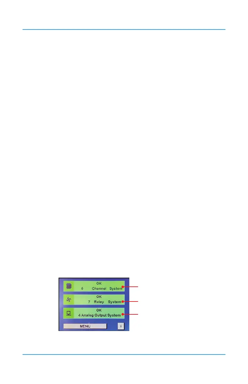
7.4.1 Summary Display (Factory Default)
The Summary view of the home screen display shows three bars on the display. The rst is
the Channel Status bar, the second is the Relay Status bar and the third is the Peripherals or
Remote Devices Status bar.
Channel Status Bar
Relay Status Bar
Peripherals or Remote
DevicesStatus Bar