© 2021 All rights reserved. Data subject to change without notice. 37
Rev. C | 2021.12 FCS - Installation Manual
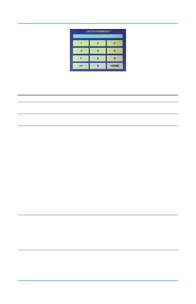
These passcodes allow for direct access to the parts of the menu system of interest:
CODE* NAME DESCRIPTION
1 Test Test Audible, Test Strobe, Test Relays, Test Analog Output
1001 Basic
Set Clock, Enable / Disable and Set Data Logger, Modbus®
Setup / BACnet® Setup
1014 Display
Congure RDM Remote Display(s)
Congure FCS Display
3022* Congure
Congure Channel Hardware
• Enable / Disable Channels
• Set Channel Communication Type (analog/digital)
• Set Channel ID
• Assign Sensor Number
Congure Channel Cong
• Set Channel Name
• Set Channel Units
• Set Channel Decimals
• Set Channel Zero
• Set Channel Range
Congure Relay Hardware
• Set Relay No
• Set Relay Modbus ID
• Set Mode (failsafe, normal, latching, not silencing)
• Enable / Disable Relays
Set ON/OFF DELAYS for Relays
3032* Analog
Congure Analog Input Hardware
• Set Modbus® ID and Channel No
• Enable / Disable Analog Input
Congure Analog Output Hardware
• Set Modbus® ID and Channel No and Type
• Enable / Disable Analog Output
*Not all passcodes or passcode menu items are listed or described in this manual. For
information on the menu items that do not appear in this manual, refer to the FCS Operation
Manual.