32 © 2021 All rights reserved. Data subject to change without notice.
FCS - Installation Manual Rev. C | 2021.12
relay coils are normally energized in non-alarm state for failsafe operation. If required,
the FCS can be congured for normal Relay operation. Refer to the FCS Operation
Manual for more information.
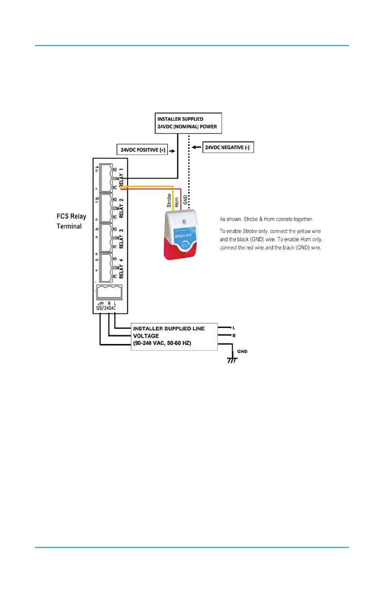
NOTE: DO NOT USE solid core wire for connection to relay terminal strip. Use stranded wire
only.
6.18 Wiring Remote Relay Connections (RLY-4 and RLY-8)
The RLY-4 Remote Relay offers four additional SPDT dry contact relays plus two horn/
strobe 24 VDC drives to a xed gas detection system. Similarly, the RLY-8 Remote Relay
offers eight additional SPDT dry contact relays plus four horn/strobe 24 VDC drives to a xed
gas detection system. The wiring is the same as described in Section 6.16 Wiring Remote
Strobe/Horn Using Output Terminal.
The remote relay devices communicate with the FCS using Modbus® communications
protocol. In the event that the connection is lost between the controller and the remote relay,
a factory congurable default state can be set to ensure the relays continue to operate as
required.