© 2021 All rights reserved. Data subject to change without notice. 23
Rev. C | 2021.12 FCS - Installation Manual
long wiring runs that may present a voltage loss condition. (If the overall length of wiring is
more than 609 m / 2,000 ft or if the area is electronically noisy, an LNK-XT Network Extender
is required to extend the range of the Modbus® RS-485 network.) The number of ESH-A
Remote Sensors used will also determine the need for remote power supply(ies).
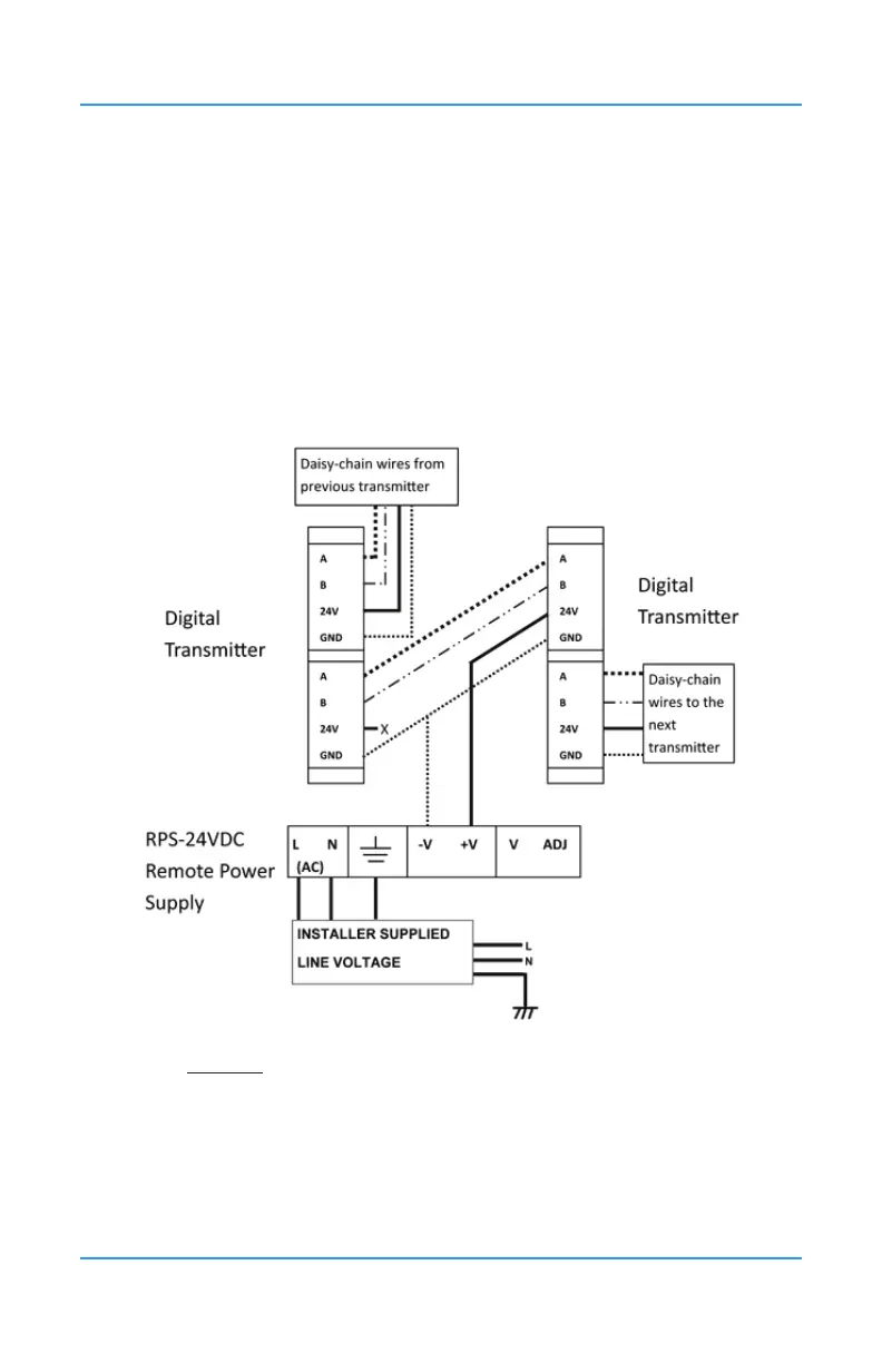
The RPS-24VDC Remote Power Supply operates from 90 to 240 VAC @ 47 to 63 Hz with
a maximum load output of 3 Amps and requires a source of line voltage power to operate.
Once installed in a long wiring run, it will provide power to the transmitters it is connected to.
The enclosure provides four mounting holes inside in the base and two ground studs inside.
NOTE: Observe polarity when connecting DC load to the output of the power supply.
For more information about the RPS-24VDC, refer to the RPS-24VDC Remote Power Supply
Operation Manual.
6.9 Wiring Internal Analog Outputs (Option -AO)
The FCS does not have any internal analog outputs unless the optional Analog Output board
has been installed (Option -AO) on the main board. Option -AO and Option -2AO are factory
installed at the time of order.
The FCS provides 24 VDC (low voltage power) to the Analog Output Terminal on the optional
-AO board, which can accommodate up to a total of eight internal analog outputs, if two