24 © 2021 All rights reserved. Data subject to change without notice.
FCS - Installation Manual Rev. C | 2021.12
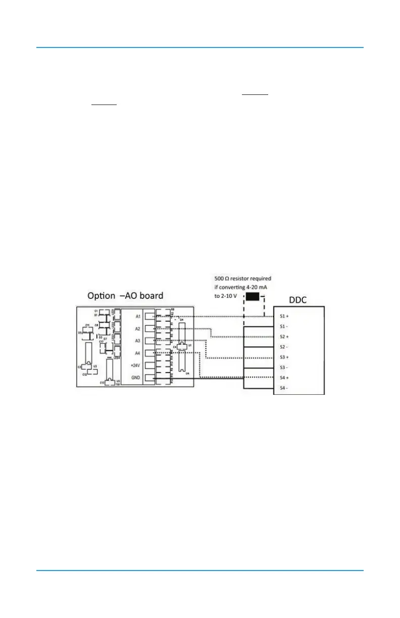
-AO boards are installed (Option -2AO). The analog output is a 4 - 20 mA current source. If
required the output can be converted to 2 - 10V by using a 500 ohm resistor in parallel.
NOTE: If two -AO boards are installed, there cannot be any internal analog inputs (Option
-AI). If required, remote analog inputs may be added by using one or more LNK-AI Peripheral
Devices connected to the LAN Terminal on the main FCS board. Refer to Section 6.12 Wiring
LNK-AI Peripheral Device (additional Analog Inputs).
A1 through A4 on the Analog Output Terminal on the -AO board provides up to four
connections designed to be used for VFD control, BAS / DDC / control panel monitoring,
connecting analog remote displays, etc. Eight connections are available if two -AO boards are
installed.
Four-conductor, 16 gauge, stranded wire / cable shielded in conduit should be used when
connecting the FCS to an analog output device. If the device is being powered by the FCS,
the voltage supplied by the FCS Controller to each remote analog device should measure
approximately 24 VDC nominal at the device. If this voltage is not attained after installation,
the wrong gauge wire may have been used or the wiring run is too long.
NOTE: Under most local electrical codes, low voltage wires cannot be run within the same
conduit as line voltage wires.
NOTE: DO NOT USE solid-core wire for connection to wiring terminal strip. Any damage
caused by using solid-core wire will void warranty. Use stranded wire pigtails 18 awg
within the enclosure to connect to the circuit board. The rigidity of solid-core wire can pull
a soldered terminal strip completely off a circuit board and this will not be covered under
warranty.