© 2021 All rights reserved. Data subject to change without notice. 43
Rev. C | 2021.12 FCS - Installation Manual
The status of a relay, horn, strobe or audible is indicated by colours and text added to the end
of the line as follows:
COLOUR ADDITIONAL TEXT DESCRIPTION
Green OK Relay, Strobe/Horn are not active
Orange Silenced
Audible device has been silenced for a
precongured amount of time, with visual
countdown
Yellow On Delay
Relay is active and has an ON Delay for a
precongured amount of time, with a visual
countdown
Orange Off Delay
Relay is active and has an OFF Delay for a
precongured amount of time, with a visual
countdown
Red Alarm Relay, Strobe/Horn has been triggered and is active
Red Latched
Relay is active and latched and requires a manual
clear
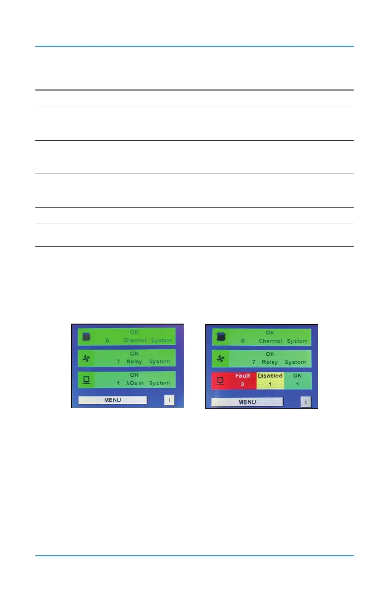
Peripherals and Remote Devices Status Bar Operation
The Peripherals Status Bar on the main display of the FCS shows a summary of the status of
the analog outputs, which includes the internal and any remote LNK-AO devices or Modbus®
VFDs. If the analog outputs are in different statuses, it will display the three most important
statuses in order from left to right. The bar will also change colour depending on the severity
of the status.
The status “Fault” is displayed in red and shows the number of devices that the FCS
cannot communicate with. The communication failure is between the FCS and an LNK-AO,
Modbus® VFD or the internal analog output connection. An example of what could cause a
“Fault” is a broken or unconnected wire.
NOTE: The FCS only communicates with the device it is immediately connected to. It does
not communicate with the device(s) the LNK-AO or the Modbus® VFD is connected to.
The status “Disabled” is displayed in yellow and species the number of analog outputs that
have been disabled. An analog output connection may be disabled for period of time to clean
or maintain the equipment that is driven by the analog output.