OPERATION AND TECHNICAL MANUAL MICRO-TEMP
®
LT, Model 749
Page 9 of 75
Table Of Figures
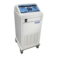
Figure 1-1 Micro-Temp
®
LT – Front View ................................................................................................................ 13
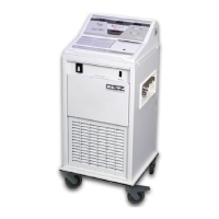
Figure 1-2 Micro-Temp
®
LT – Rear View .................................................................................................................. 15
Figure 1-3 Micro-Temp
®
LT – Membrane Control Panel (100V/115V Only) ............................................................. 17
Figure 1-4 Micro-Temp
®
LT – Membrane Control Panel (230V/240V Only) ............................................................. 17
Figure 5-1 Micro-Temp
®
LT –Exposed Rear View .................................................................................................... 43
Figure 6-1 Micro-Temp
®
LT Internal Exploded - Front View .................................................................................... 64
Figure 6-2 Micro-Temp
®
LT - Parts List A ................................................................................................................. 64
Figure 6-3 Micro-Temp
®
LT – Internal Exploded – Rear View .................................................................................. 65
Figure 6-4 Micro-Temp
®
LT - Parts List B ................................................................................................................. 65
Figure 6-5 Micro-Temp
®
LT Reservoir – Side View .................................................................................................. 66
Figure 6-6 Micro-Temp
®
LT - Parts List C ................................................................................................................. 66
Figure 6-7.A Micro-Temp
®
LT Electrical Wiring Diagram – 100V/115V .................................................................... 67
Figure 6-7.B Micro-Temp
®
LT Electrical Wiring Diagram – 230V/240V .................................................................... 68
Figure 6-8 Micro-Temp
®
LT Accessories .................................................................................................................. 69
Table 1 Guidance and Manufacturer’s Declaration – Electromagnetic Emissions .................................................... 72
Table 2 Guidance and Manufacturer’s Declaration – Electromagnetic Immunity .................................................... 72
Table 3 Guidance and Manufacturer’s Declaration– Electromagnetic Immunity that is not used for Life Support .. 73
Table 4 – Recommended Separation Distances Between Portable and Mobile RF Communications Equipment and
the Micro-Temp
®
LT, Model 749 ............................................................................................................................. 74