2 — INSTALLATION AND WIRING
pg. 7
Return to TOC Curtis AC F4-A Motor Controller – August 2020
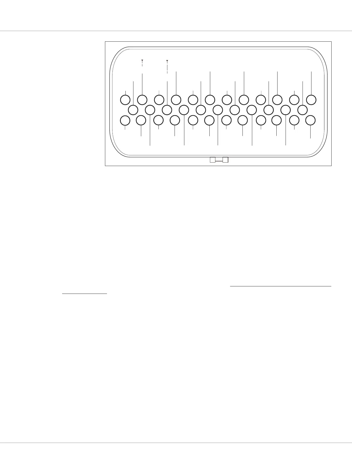
35 34 33 32 31 30 29 28 27 26 25 24
12 11 10 9 8 7 6 5 4 3 2 1
23 22 21 20 19 18 17 16 15 14 13
CAN1 L
CAN 1
TERM L
CAN1 H
INPUT 8
INPUT 4
ENC 1B
INPUT 3
ENC 1A
DRIVER 8
CAN2 L
CAN2 H
INPUT 19
POT 19 SUPPLY
INPUT 31
+5V SUPPLY
INPUT 14
+12V SUPPLY
INPUT 9
KSI
DRIVER 1
INPUT 21
DRIVER 4
INPUT 24
DRIVER 3
INPUT 23
DRIVER 2
INPUT 22
DRIVER 5
INPUT 25
GND
INPUT 2
MOTOR TEMP
INPUT 5
INPUT 10
(PWM)
INPUT 11
ENC 1C
INPUT 12
ENC 2A
INPUT 7
CAN 1
TERM H
DRIVER 7
INPUT 27
DRIVER 6
INPUT 26
GND
INPUT 18
POT 18 WIPER
INPUT 1
POT 1 WIPER
INPUT 6
POT 6 SUPPLY
INPUT 13
ENC 2B
COIL
SUPPLY
ISOLATED GROUND
MODELS w/ Isolated CAN
NOT USED ON
MODELS w/ Isolated CAN
Figure 5
35-Pin AMPSEAL
Connection Assignments
e 35-pin Input and Outputs (I/O) assignments in Figure 5 follow the basic wiring diagram of Figure 6.
Figure 5’s orientation is looking at the controller, which is also the harness-side of the connector. When
designing a vehicle harness and its routing throughout a vehicle, follow these guidelines to avoid common
control-signal interference. Protect the wiring from abrasions due to vibrations, pinch, cut and pull-lose
damage, which can lead to an inoperative controller. Reference Appendix B, Vehicle Design Considerations
for EMC guidelines.
Rotor Position feedback (Pins 18, 26, 31, 32)
e rotor-position sensor’s wiring (+5V, Feedback A, Feedback B, and Ground) should be bundled together
between the motor and controller. ese wires are oen run with the rest of the low current wiring harness
without interference issues, but the encoder wires should not be routed near the motor cables. In applications
where this is not possible or there is signal interference, twist the encoder signal wires. In cases using a
shielded cable (e.g., shielded 2-wire twisted-pair with drain-wire), only ground the shield-drain wire at the
controller ground (pin 18).
CANbus (Pins 21, 34 and 28, 29)
Use twisted-pair wires for the CANbus connections. Keep the CAN wiring away from the high current cables
and cross them at right angles when necessary. In extreme cases, use shielded cable with the shield connected
to the ground (pin 7) only on the controller side for the non-isolated controller models.
Two CAN ports allow the implementation of both 11-bit identiers (CANopen) and 29-bit identiers (e.g.,
J1939), and/or dierent baud rates to support a high-speed CANbus for safety or data logging.
An isolated CAN option uses a separate (isolated) CANbus ground reference, which is useful on vehicles with
CANbus systems operating at dierent battery voltages. It avoids common mode noise issues. e isolated
ground (pin 34) is provided for twisted pair shielding, and may not be needed. When using shielded wiring,
only connect the shield’s drain-wire to pin 34. e option always includes both CAN1 and CAN2 as isolated
CAN.
 Loading...


