2 — INSTALLATION AND WIRING
Curtis AC F4-A Motor Controller – August 2020 Return to TOC
pg. 18
Drivers 6 and 7 are lower-current digital (On/O) drivers. Use the drivers for dashboard LEDs,
piezo-electric buzzers and other low-current switched loads (i.e., high input impedance devices able
to accept full coil supply voltage).
e F4 controller has two special purpose drivers.
• Driver 1 supports proportional valves, oering a higher frequency and ner current accuracy
in addition to the typical dither-related parameters. e proportional driver’s minimum duty
cycle is 11%, because the current regulation is unavailable below this percentage.
• Driver 2 supports a 3A load for EM Brake usage.
Table 8 summarizes the drivers. Drivers 2–5 also support dither and current control, albeit at an
accuracy of 15%. e parameter Driver_Output_Frequency collectively sets the PWM frequency for
Drivers 2–5, whereas Driver 1 is xed. To implement additional driver controls, use VCL. As noted
in Table 5, these drivers are congurable as switch inputs, and are included in that group as well
(inputs 21–27).
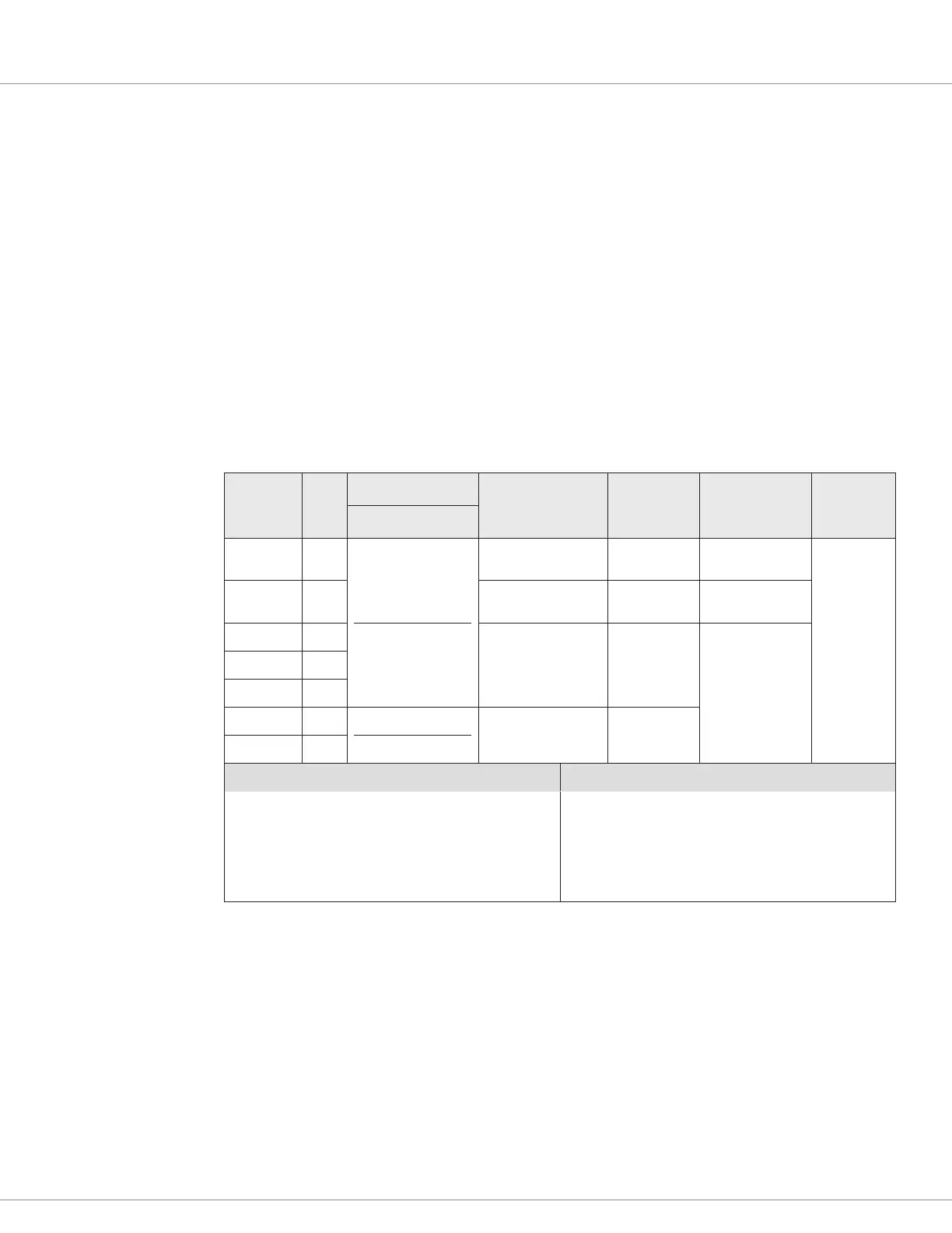
Table 8 Driver Outputs Electrical Specifications
Input
Signal
Name
Pin
Switching Side
PWM (Duty Cycle)
Frequency
Output
Current
2
Current
Measurements
3
Input
Impedance
Driver 1 2
Low-Side (only)
0-100% selectable
6
18 kHz
(xed, ± 500 Hz)
2 Amps 40 mA – 2.6 A
4
> 30k Ω
Driver 2 5
200 – 2000 Hz
1
(adjustable)
3 Amps 450 mA – 3.9 A
4
Driver 3 4
200 – 2000 Hz
1
(adjustable)
2 Amps
40 mA – 2.6 A
4
Driver 4 3
Driver 5 6
Driver 6 19
Low-Side (only)
5
0 or 100% (On/Off)
18 kHz
(xed, ± 500 Hz)
1 Amp
Driver 7 20
VCL Functions VCL Monitor Variables
Automate_Driver( )
Put_Driver( )
Battery_Compensate( )
—
Driver_Output_Frequency
Driver_Output_Frequency
Driver_Pwm
Driver_Voltage
Driver_Pwm_Pull_In_And_Hold
Driver_Voltage_Pull_In_And_Hold
Driver_Current
1
The PWM Frequency parameter collectively sets Drivers 2–5 frequency (± 10%).
2
The sum of all driver currents shall not exceed Coil Supply (pin 13) current rating.
3
2–130% of continuous rating. Minimum duty-cycle of 10% required for current measurement.
4
Over-current shut down occurs at 120% of current rating in < 8 ms | 200% < 1 ms
5
Output Low Voltage: < 0.25V at full current and 100% PWM.
6
Proportional Driver 1, the minimum current regulation is 11% duty cycle (operate > 11% duty cycle).
Coil impedance affects the lower limit of current control, where I = (11% PWN x Bat Voltage)/Coil Impedance (i.e., simplified
steady state conditions, as the basic starting point of the proportional drivers current regulation limit).
 Loading...


