6 — COMMISSIONING
Curtis AC F4-A Motor Controller – August 2020 Return to TOC
pg. 134
a) Set the Forward and Reverse input sources. See Programmer » Controller Setup » IO Assignments
» Switch Assignment » Forward Input Source and Reverse Input Source. ese are numbered
switch assignments, viewable n the Switch Status menu when they are cycled On/O.
See Figure 6 and the Programmer » Controller Setup » Switch Status menu.
Note, the switch status is also viewable in the Programmer » System Monitor » Switch Status menu.
b) Set the rottle Source, which for voltage, 3-wire, or 2-wire throttles will be the Analog 1 input—
set by inputting 1 for the rottle Source parameter. See Programmer » Controller Setup » IO
Assignments » Controls » rottle Source. If using a VCL rottle source, change the rottle
Source from the default 1 to 0, even though it ignores this throttle source when enabling the VCL
rottle parameter (see Step e, below).
c) When the Throttle Source will use Analog 1 input (pin 16), next set the type of input—
Voltage, 3-wire, or 2-wire from the pull-down menu. See Programmer » Controller Setup »
Inputs » Analog 1 Type. Based upon the throttle type selected, that type’s parameters and
sub-menu will become visible, allowing targeted setup. See the voltage and potentiometer
throttle setups (below).
Within the Inputs menu, if using a PWM output signal position sensor throttle, select the
PWM Input 10 Type parameter, and then the sensor’s appropriate duty cycle or frequency
parameters in the PWM Input 10 menu (in the Analog list).
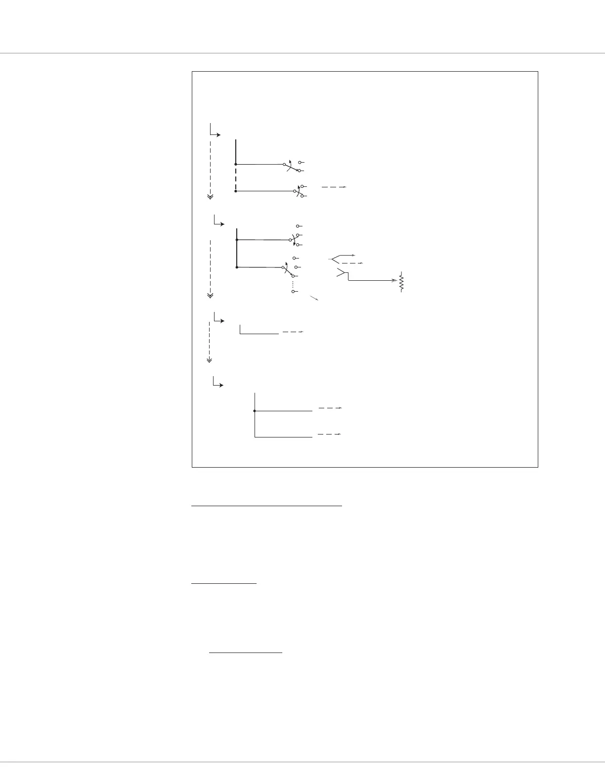
Throttle
Direction Source
FWD/REV Switches
Wigwag
Inputs
Throttle_Command comes from VCL_Throttle.
Voltage
3Wire Pot
2Wire Pot
Application Setup
Controller Setup
VCL Throttle Enable
Off
On
Analog 1 Type
Curtis Integrated Toolkit™ >> Programmer
Controls
IO Assignments
Throttle Assignment.
Assigns which analog input is the wired-throttle (potentiometer or voltage).
Default uses Analog 1 (i.e., pin 16).
Switch Assignments
IO Assignments
Throttle Source
Forward Input Source
Reverse Input Source
Forward Switch Assignment.
Number is limited by available switches as per Controller model.
Example: Switch 7 (pin 22) = FORWARD. See wiring diagram(s).
Reverse Switch Assignment.
Number is limited by available switches as per Controller model.
Example: Switch 8 (pin 33) = REVERSE. See wiring diagrams(s).
process via VCL (VCL_Throttle_Pot), as/if used.
Potentiometer 1
Set the Nominal Resistance of the throttle pot.
Typically 1k, 5k, or 10k Ω.
Set Min (0% throttle) and Max (100% throttle) parameters.
pin-16 input
Voltage with Supply
not applicable for the throttle.
PWM Input 10 Type
PWM position-sensor throttles.
Frequency
Duty Cycle
}
Not used
0
1
2
pin-10 input
Figure 24
rottle Related Parameters –
Setup Options
Quick Links:
Fig. 6 p.10
Fwd/Rev Source p.100
Switch Status p.102
rottle Source p.100
VCL rottle Enable p.49
Inputs p.85
 Loading...


