2 — INSTALLATION AND WIRING
Curtis AC F4-A Motor Controller – August 2020 Return to TOC
pg. 20
Keyswitch and Coil Supply
Connect the Keyswitch (KSI) input to B+ via a key switch. e keyswitch input (pin 1) feeds the
controller’s internal power supplies, the Coil Supply output, and the main-capacitor bank’s precharge
(before the main contactor closes). The lead-acid Battery Discharge Indicator (BDI) uses the
keyswitch voltage.
Always connect the Coil Supply circuits (i.e., the contactors’ B+ source) directly to the positive
side (+) of the contactors’ coil terminals so that the electrical-switching-noise associated with low-
side drivers’ pulse width modulation (PWM) operation are localized to the contactor wiring only.
e controller includes an internal y-back diode between each Driver and Coil Supply to suppress
the coils’ inductive voltage spike. Coils with their own inductive-spike suppression diodes are allowed,
yet resistive means are discouraged because of leakage currents. Note, the cumulative sum of the
Driver 1 through Driver 7 currents shall not exceed the Coil Supply’s maximum continuous current
rating (see Table 10, below).
It is important to maintain the division between KSI and Coil Supply in order to ensure reverse
polarity protection (vehicle wiring correct, battery terminals reversed). Reference the wiring
diagrams, Figures 6 & 7, for the KSI and Coil Supply connections.
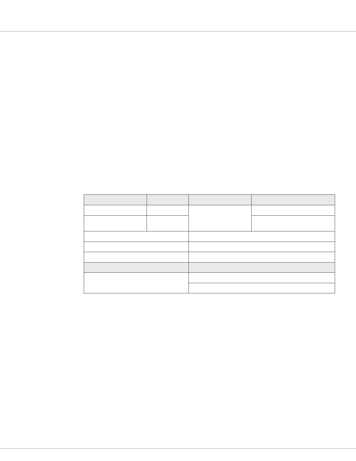
Table 10 Keyswitch and Coil Supply Electrical Specifications
Signal Pin Operating Voltage Input Current
Keyswitch (KSI) 1
Between the under and
overvoltage cutback limits
12 Amps
1
Coil Supply 13
12 Amps
1
24V Models
10 Amps
1
36-48V Models
AMPSEAL Connector Current Ratings 12 Amps per pin (Maximum, continuous)
KSI Inrush Current 10 Amps, Max, ≤ 2 milliseconds overall, with initial peak ≤ 20 us, 25°C
Precharge Current 2 Amps for < 1 sec (typical)
VCL Functions VCL Monitor Variables
Keyswitch_Voltage
Coil_Supply
1
Includes current from the Coil Supply (full driver usage). Gold plated terminal basis, default models.
Tin plated terminals will have reduced current rating, i.e., 8 Amps. (On special models, so equipped with Tin pins.)
 Loading...


