2 — INSTALLATION AND WIRING
Curtis AC F4-A Motor Controller – August 2020 Return to TOC
pg. 10
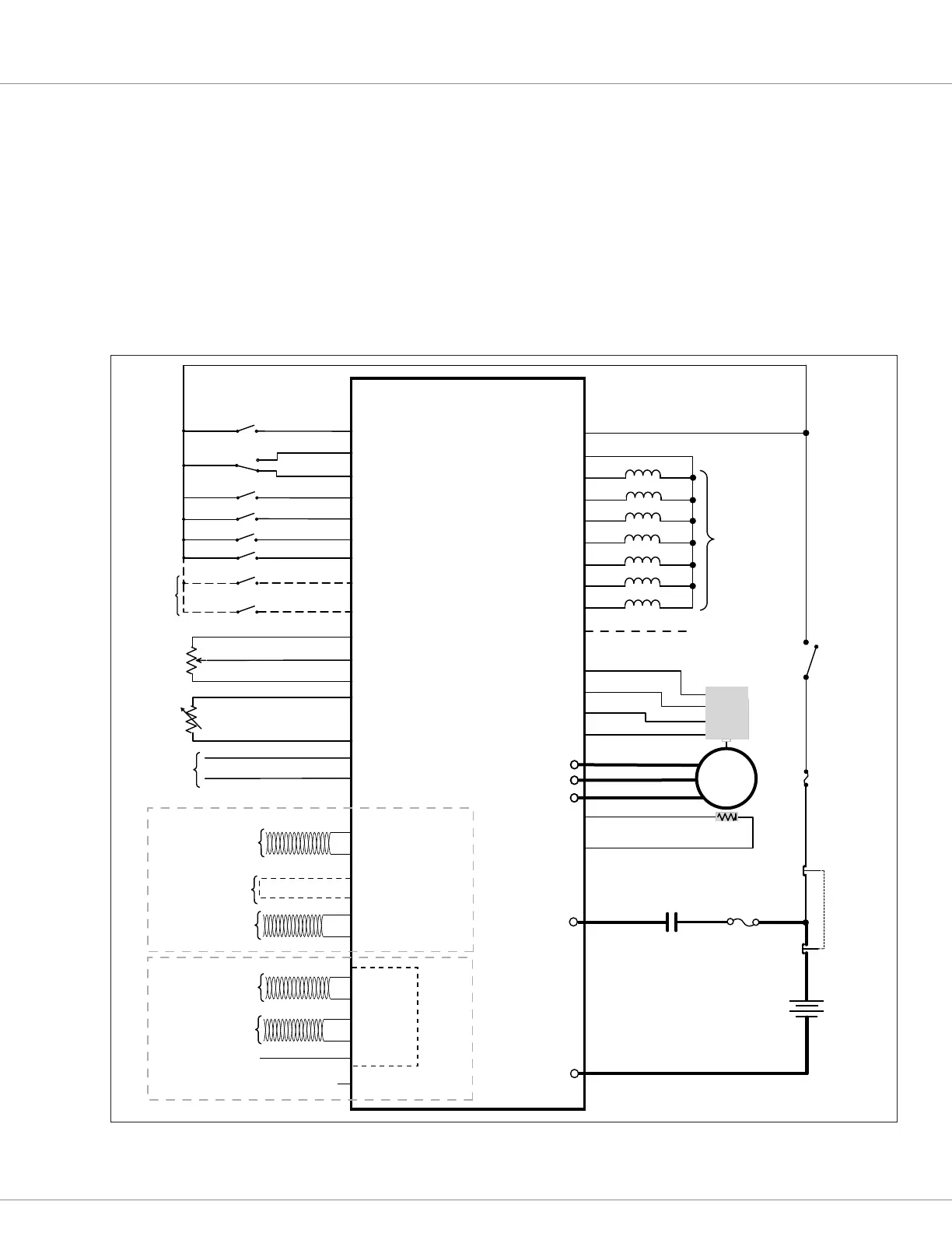
Controller Wiring Diagram (Examples)
Figure 6 illustrates the F4-A controller wiring for a Class III pallet truck using wired inputs from
switches and potentiometers, driving an induction traction motor. e Interlock, Forward, Reverse,
Li, Lower, and the redundant Emergency Reverse inputs are by external mechanical switches pulled
to KSI (B+). e traction motor feedback is a quadrature encoder and the throttle input is a 3-wire
potentiometer (which meets EEC fault protection). Beyond these assigned I/O usages, the available
(non-assigned) switch inputs, drivers, and the analog output, are programmable to suit a diverse
range of F4-A controller applications.
Figure 6 illustrates both the non-isolated and isolated CAN port options. See Appendix E for the
controller models and specications, which support these options.
Quick Links:
Appendix E p.205
NO
NC
Emergency
Reverse
Lower
Interlock
User Input
E Stop
Pole A
U
V
W
Speed/
Position
Sensor
GND
Input 2 / Motor Temp
Motor Temp
Sensor
Fuse
Load-Hold Valve
Ext. Load 2
Proportional Valve
Optional
Peripherals
Safety Disabled
and
Reverse Polarity
Protected
Loads
Input 8
Input 9
Input 7
Input 19 / Pot 19 Supply
Input 13 / Enc 2B
Input 10 (PWM)
Input 11 / Enc 1C
Input 5
Input 12 / Enc 2A
KSI
Input 31 / +5V
Input 3 / Enc 1A
Input 4 / Enc 1B
GND
Coil Supply
Driver 4 / Input 24
Driver 3 / Input 23
Driver 5 / Input 25
Driver 6 / Input 26
Driver 7 / Input 27
Driver 1 / Input 21
Driver 2 / Input 22
Driver 8
Analog Output
AC
Induction
Motor
5V
A/Sin
B/Cos
GND
18
Lift
Reverse
Forward
18
Key-Switch
Ext. Load 1
Main Coil
Ext. Load 3
EM Brake
1
26
31
32
8
10
22
9
13
Travel Limit
4
3
2
5
6
19
20
27
33
24
14
30
11
12
External
Power
Supply
Input 31 / +5V Ext Supply
Input 14 / +12V Ext Supply
26
25
Input 18 / Pot 18 Wiper
GND
Brake
Throttle
Input
7
17
Traction
Motor
Throttle
Input
Input 6 / Pot 6 Supply
Input 1 / Pot 1 Wiper
GND
7
16
15
B+
Main Contactor
Battery
-
+
Fuse
B–
EMERGENCY
STOP
E Stop
Pole B
+ –
CAN PORT #2*
CAN2 L
CAN2 H
Short for
Termination
120Ω CAN1
34
21
28
29
twisted pair, recommended
CAN PORT #1
CAN1 H
CAN1 L
23
35
twisted pair, recommended
CAN PORT #1
CAN1 H
CAN1 L
Isolated GND
23
35
34
CAN2 L
CAN PORT #2
CAN2 H
28
29
twisted pair, recommended
ISOLATED
CAN PORTS
21
Not Used
ISOLATED CAN MODELS
MODELS W/O ISOLATED
CAN
twisted pair, recommended
Figure 6
AC F4-A Basic Wiring Diagram
 Loading...


