2 — INSTALLATION AND WIRING
pg. 11
Return to TOC Curtis AC F4-A Motor Controller – August 2020
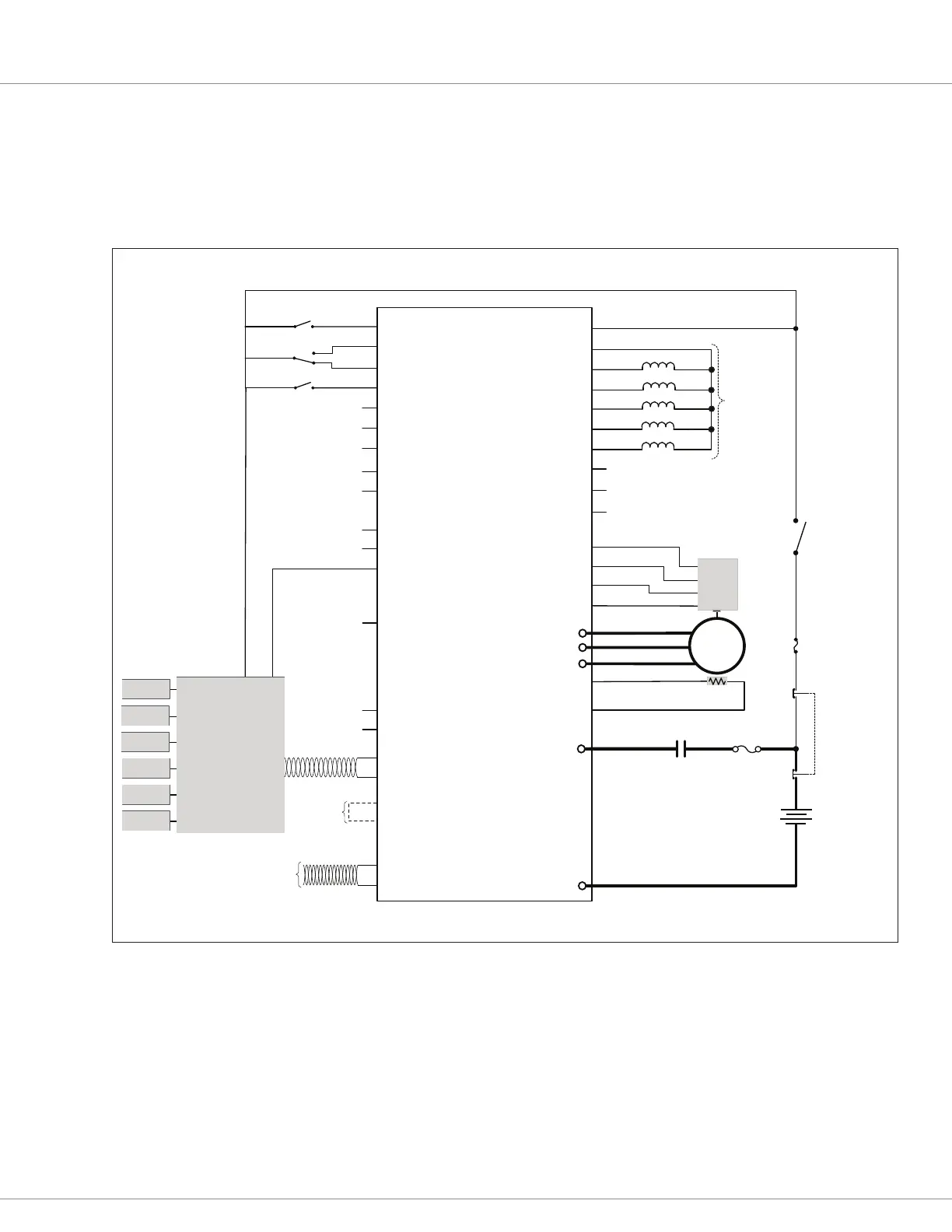
For CANopen based tiller heads (or similar), see the Figure 7 wiring example. In this CAN-based
example, the Interlock, Emergency Reverse, and a Travel Limit are the remaining “wired” switch
inputs. e CAN communication between the tiller and controller is always on CAN1.
Figure 7a illustrates the isolated CANbus option.
NO
NC
Emergency
Reverse
Interlock
Tiller-Head
Controller
Throttle
CAN 1
Power
Supply
Lower
Lift
Horn
Reverse
Forward
KSI
Input 8
Input 9
Input 7
AC
Induction
Motor
Input 31 / +5V
Input 3 / Enc 1A
Input 4 / Enc 1B
GND
Speed
Position
Sensor
Fuse
Coil Supply
Driver 4 / Input 24
Driver 3 / Input 23
Driver 5 / Input 25
Load-Hold Valve
Driver 6 / Input 26
Driver 7 / Input 27
Input 6 / Pot 6 Supply
Input 1 / Pot 1 Wiper
GND
Input 18 / Pot 18 Wiper
Input 19 / Pot 19 Supply
Driver 1 / Input 21
Driver 2 / Input 22
Proportional Valve
Input 13 / Enc 2B
Input 10
Input 11 / Enc 1C
Input 5
Input 12 / Enc 2A
Input 31 / +5V Ext Supply
Input 14 / +12V Ext Supply
CAN1 H
CAN1 L
CAN 2L
CAN 2H
Driver 8
Main Contactor
5V
A/Sin
B/Cos
GND
18
Travel
Limit
18
Key-Switch
Horn
Main Coil
7
EM Brake
26
31
32
8
16
22
26
9
13
23
35
28
29
4
3
2
5
6
19
2027
33
24
14
30
10
11
12
25
17
15
1
-
+
Safety Disabled
and
Reverse Polarity
Protected
Loads
34
21
Connect for
Termination
120Ω CAN1
CAN PORT #2
Fuse
twisted pair, recommended
EMERGENCY
STOP
E Stop
Pole A
E Stop
Pole B
Battery
B+
B–
U
V
W
GND
Input 2 / Motor Temp
Motor Temp
Sensor
+
−
twisted pair, recommended
Figure 7
AC F4-A CAN Tiller Head Wiring Diagram
 Loading...


