2 — INSTALLATION AND WIRING
Curtis AC F4-A Motor Controller – August 2020 Return to TOC
pg. 8
All other low power wiring
Use standard vehicle-harness routing practices for the remaining connections. When designing the
vehicle’s wiring and routing, keep the inputs such as the throttle, temperature, and the motor feedback
signals separate from controller’s output lines such as the coil driver outputs. Avoid routing the low-
power wiring parallel to the high power (and high current) battery and motor cables.
Protected voltages
e low-power pins’ protected voltage ratings listed in Table 3 are absolute and are not for normal
operation. To prevent damage to the controller, do not connect (i.e., short circuit) the Coil Supply
(pin 13) to battery negative. Further, do not connect (i.e., short circuit) the I/O Ground (pins 7 &
18) to battery positive.
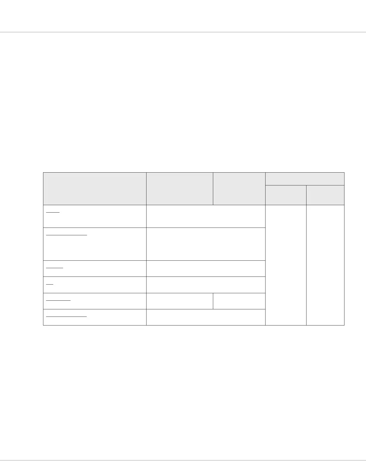
Table 3 AMPSEAL Connections Protected Voltages
Controller I/O
Pin Number
Min (reverse)
Voltage
Maximum
Voltage
ESD
Air Discharge
(non-contact)
Contact
(touch)
Inputs
8, 9, 10, 11, 12, 14, 15, 16, 17, 22, 24, 25,
26, 27, 31, 32, 33
Indenite short to B+ and B–
±15kV ±8kV
CAN (non-isolated)
21, 23, 28, 29, 34, 35
CAN (isolated)
23, 28, 29, 34, 35
Indenite short to B+ and B–
Outputs
2, 3, 4, 5, 6, 19, 20, 25, 26, 30
Indenite short to B+ and B–
KSI
1
Indenite short to B+ and B–
Coil Supply
13
Not Protected against
short to B–
Indenite short to
B+
GND or I/O Ground
7, 18
Not protected
 Loading...


