6
Curtis 1222 Manual, os 15
2 9 J A N U A R Y 2 0 1 3 D R A F T
2 — INSTALLATION & WIRING: High Current Connections
HIGH CURRENT CONNECTIONS
There are five high-current terminals, identified on the controller housing as
B+, B-, U, V, and W.
Table 1 High Current Connections
TERMINAL FUNCTION
B+ Positive battery to controller.
B- Negative battery to controller.
U AC steer motor phase U.
V AC steer motor phase V.
W AC steer motor phase W.
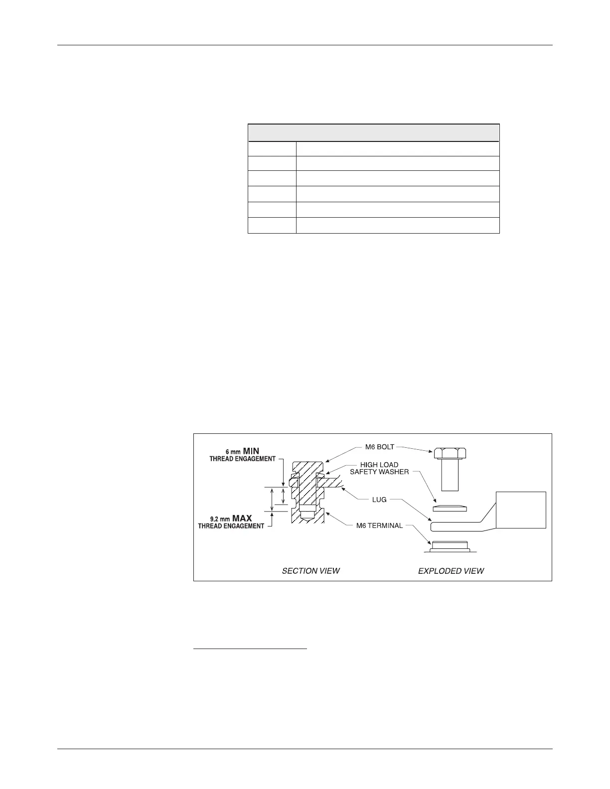
Lug assembly
Five aluminum M6 terminals are provided. Lugs should be installed as follows,
using M6 bolts sized to provide proper engagement (see diagram):
• Place the lug on top of the aluminum
terminal, followed by
a high-load safety washer with its convex side on top. The
washer should be a
SCHNORR 416320, or equivalent.
• If two lugs are used on the same
terminal, stack them so the
lug carrying the least current is on top.
• Tighten the assembly to 10.2 ±1.1 N·m (90 ±10 in-lbs).
High current wiring recommendations
Battery cables (B+, B-)
These two cables should be run close to each other between the controller
and the battery. Use high quality copper lugs and observe the recommended
torque ratings. For best noise immunity the cables should not run across the
center section of the controller. With multiple high current controllers, use a
star ground from the battery
B- terminal.