Curtis 1222 Manual, os 15
37
2 9 J A N U A R Y 2 0 1 3 D R A F T
POSITION FEEDBACK DEVICE 0 – ANALOG5 and 6
ALLOWABLE
PARAMETER RANGE DESCRIPTION
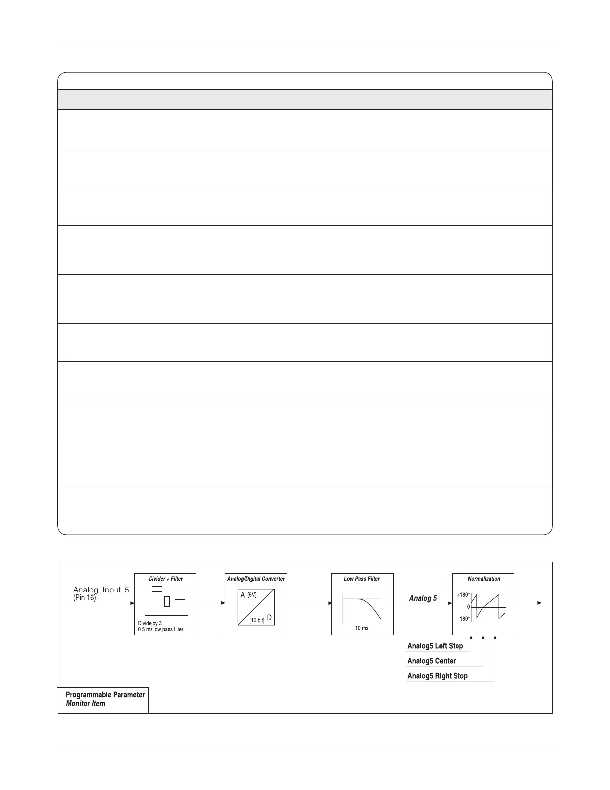
Analog5 Left Stop 0 – 10.00 V
•
n
Defines the Analog 5 wiper voltage when the steer position feedback
0x407F 0x00 0 – 1023 is at the Left Stop (Wheel Position = Left Stop).
Analog5 Center 0 – 10.00 V
•
n
Defines the Analog 5 wiper voltage when the steer position feedback
0x4081 0x00 0 – 1023 is at the center position (Wheel Position = 0°).
Analog5 Right Stop 0 – 10.00 V
•
n
Defines the Analog 5 wiper voltage when the steer position feedback
0x4080 0x00 0 – 1023 is at the Right Stop (Wheel Position = Right Stop).
Analog5 Fault Min 0 – 10.00 V Sets the minimum threshold for the Analog 5 steer position feedback pot.
0x40AE 0x00 0 – 1023 If the Analog 5 steer position feedback pot voltage falls below this
threshold for 60 ms, a fault is issued.
Analog5 Fault Max 0 – 10.00 V Sets the maximum threshold for the Analog 5 steer position feedback pot.
0x40AF 0x00 0 – 1023 If the Analog 5 steer position feedback pot voltage rises above this
threshold for 60 ms, a fault is issued
Analog6 Left Stop 0 – 10.00 V
•
n
Defines the Analog 6 wiper voltage when the steer position feedback
0x40A3 0x00 0 – 1023 is at the Left Stop (Wheel Position = Left Stop).
Analog6 Center 0 – 10.00 V
•
n
Defines the Analog 6 wiper voltage when the steer position feedback
0x4082 0x00 0 – 1023 is at the center position (Wheel Position = 0°).
Analog6 Right Stop 0 – 10.00 V
•
n
Defines the Analog 6 wiper voltage when the steer position feedback
0x40A4 0x00 0 – 1023 is at the Right Stop (Wheel Position = Right Stop).
Analog6 Fault Min 0 – 10.00 V Sets the minimum threshold for the Analog 6 steer position feedback pot.
0x4011 0x00 0 – 1023 If the Analog 6 steer position feedback pot voltage falls below this
threshold for 60 ms, a fault is issued.
Analog6 Fault Max 0 – 10.00 V Sets the maximum threshold for the Analog 6 steer position feedback pot.
0x4012 0x00 0 – 1023 If the Analog 6 steer position feedback pot voltage rises above this
threshold for 60 ms, a fault is issued.
3 — PROGRAMMABLE PARAMETERS: Position Feedback
Parameters
Fig. 10 Position Feedback Device “0” signal flow (Analog 5 shown; Analog 6 is similar).
PCF
RIS