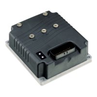
Curtis 1222 Manual, os 15
15
2 9 J A N U A R Y 2 0 1 3 D R A F T
Keyswitch input and coil return
Keyswitch power to the 1222 is provided through the coil return of the traction
controller. This ensures that the steer controller is not turned Off unless the
traction controller is Off. Both controllers shut down in the event of a fault.
Coil suppression for the traction controller is provided when the traction
main contactor and EM brake are wired to the fault output (pin 24). However,
you may wish to use coil suppression diodes to reduce EMI emissions.
Coil Return should be wired to the positive battery side of the steer
contactor so that switching noise associated with PWM operation of the
contactor is localized to the contactor wiring only.
Reverse polarity protection is ensured only when the keyswitch input and
coil return are wired as shown in Figure 3a (page 11).
.
2 — INSTALLATION & WIRING: I/O Signal Specifications
Communications ports
Separate CAN and serial ports provide complete communications and program-
ming capability for all user available controller information.
Note: The 1222 controller has no internal 120
Ω CAN terminating resis-
tor. Typically the wiring of the CAN bus nodes is a daisy chain topology with
120Ω CAN terminating resistors at each end. If the vehicle wiring is done such
that the 1222 is the last node in the chain, then an external 120
Ω terminating
resistor should be provided by the OEM in the wiring harness.
The Curtis programmer plugs into a connector wired to pins 28 and 29,
along with ground (pin 7) and the +10V power supply (pin 15); see wiring
diagram, Figure 3a.
KEYSWITCH AND COIL RETURN INPUT SPECIFICATIONS
OPERATING
MAX INPUT PROTECTED ESD
SIGNAL NAME PIN VOLTAGE
CURRENT VOLTAGE TOLERANCE
Keyswitch 1 Between under- 50–500 mA 65 V ± 8 kV (air
and overvoltage + coil return current discharge)
Coil Return 13
cutbacks
10 A
65 V
COMMUNICATIONS PORT SPECIFICATIONS
SUPPORTED
PROTECTED ESD
SIGNAL NAME PIN PROTOCOL/DEVICES
DATA RATE VOLTAGE TOLERANCE
CAN High 23 CANopen up to 1 Mbps -5 V to ± 8 kV (air
CAN Low 35 (MaxV + 10 V) discharge)
with < 30 V
differentially
Tx 28
1313 Handheld as required, -0.3 to 12 V ± 8 kV (air
Rx 29
Programmer, 9.6 to 56 kbps discharge)
1314 PC Program-
ming Station

 Loading...