Curtis 1222 Manual, os 15
11
2 9 J A N U A R Y 2 0 1 3 D R A F T
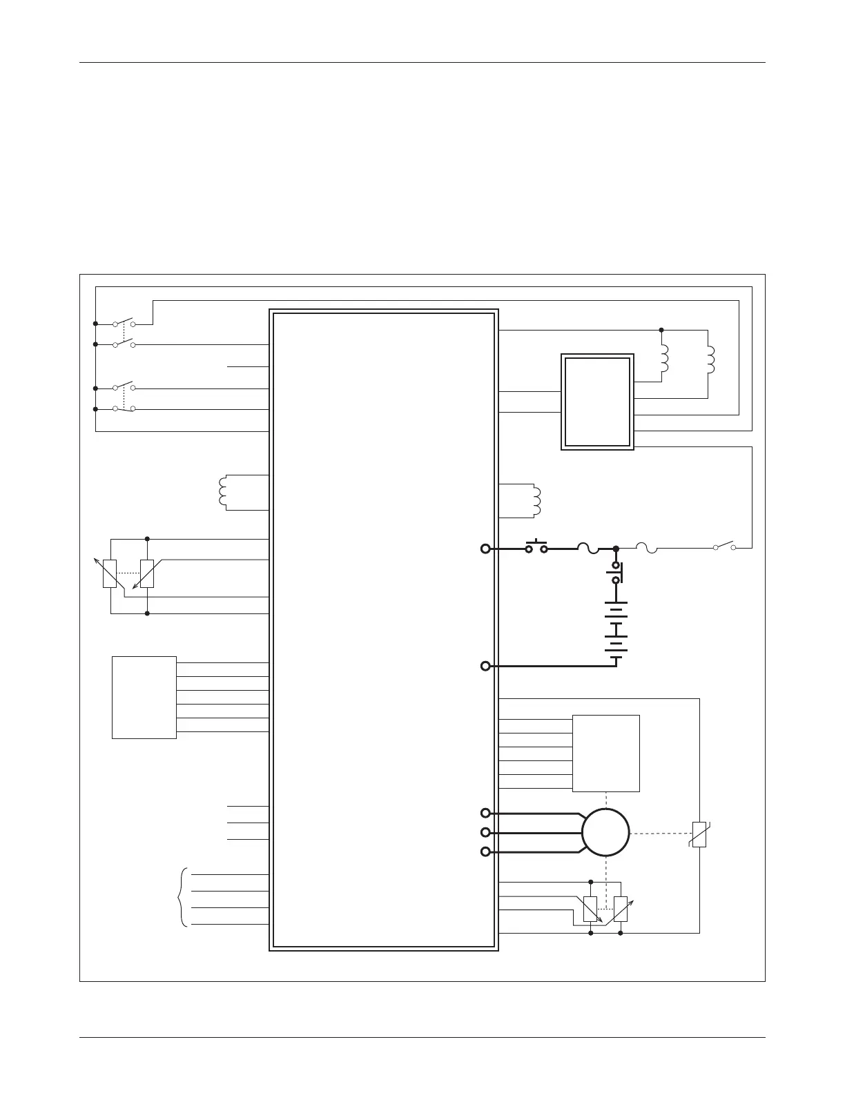
Fig. 3a Wiring diagram, Curtis 1222 electric steering controller.
2 — INSTALLATION & WIRING: Controller Wiring
CONTROLLER WIRING: Safety Requirements
As shown in the wiring diagram (Figure 3a), the 1222’s keyswitch power must
go through the traction controller so that when the keyswitch is turned off both
controllers turn off. The fault output (Pin 24) should be able to shut down
the traction system in the case of a serious fault; otherwise the system may not
meet the international safety requirements listed in Table D-1.
As shown in the wiring diagram, two steer command devices and two
position feedback devices are used. The 1222 supervises and matches each
1222 CONTROLLER
J1-8
J1-21
Home Input 4
J1-12
Home Input 2
J1-10
Interlock Input 3
J1-11
Interlock Input 1
J1-9
Command Encoder 1A
J1-14
Command Encoder 1B
J1-25
Command Encoder 2A
J1-33
Command Encoder 2B
J1-20
Ground
J1-18
AC
STEER
MOTOR
J1-1
Keyswitch
STEER MOTOR
ENCODER 3
and
ENCODER 4
**
J1-31
J1-32
J1-26
J1-27
J1-2
J1-24
J1-15
J1-28
J1-29
J1-7
SERIAL
SERIAL PORT
(4-pin Molex)
4
3
1
2
KEYSWITCH
V
Steer Motor Encoder 3A
Steer Motor Encoder 4A
Fault Output
+10V
RX
Ground
U
W
Steer Motor Encoder 3B
Steer Motor Encoder 4B
Contactor Driver
BATTERY
(24–48V)
B+
B-
TX
EMERGENCY
STOP
+5V
J1-21
J1-23
J1-35
CAN Low
CAN High
CURTIS
AC
TRACTION
CONTROLLER
J1-19
J1-18
Command Analog 3
Command Analog 1
+5V
Ground
STEER
COMMAND
ENCODER 1
and
ENCODER 2
*
J1-34
J1-16
J1-17
J1-7
+5V
Position Analog 6
Position Analog 5
Ground
STEER COMMAND
POTS
*
Reserved
J1-3
Reserved
J1-4
Force Feedback Driver
J1-5
MOTOR
TEMPERATURE
SENSOR
POSITION
FEEDBACK
POTS
**
J1-34
+5V
J1-30
Ground
STEER
CONTACTOR
J1-13
Coil Return
J1-6
EM BRAKE
TRACTION
MAIN
CONTACTOR
STEER
CONTACTOR
J1-5
J1-13
J1-1
J1-23
J1-35
N.O.
N.C.
**
Encoder 4 is not used if
the feedback pots are used.
Reserved
J1-6
J1-9
J1-22
Motor Temp Sensor
*
Mutually exclusive;
use either pots or encoders.
INTERLOCK SWITCH
HOMING SWITCH
†
†
†
An external 120Ω resistor may
be required at the 1222 end of
the CAN bus; see page 15.
FORCE
FEEDBACK
COIL
Coil Return
J1-13