14
Curtis 1222 Manual, os 15
2 9 J A N U A R Y 2 0 1 3 D R A F T
Analog inputs
The command and position analog inputs are used when the steer command and
position feedback devices are pots or sine/cosine sensors or sawtooth sensors.
The motor temperature sensor input provides a constant current appro
-
priate for a thermistor sensor. Some standard predefined motor temperature
sensors are supported in software (see Sensor Type parameter, page 49). Note:
The industry standard KTY temperature sensors are silicon temperature sensors
with a polarity band; the polarity band of a KTY sensor must be the end
connected to I/O Ground (pin 7).
All analog inputs are protected against shorts to B+ or B-.
2 — INSTALLATION & WIRING: I/O Signal Specifications
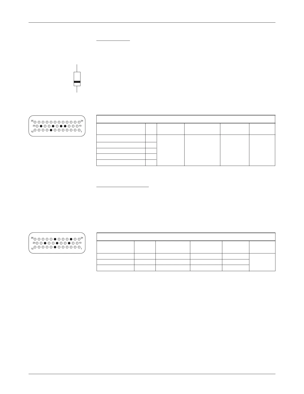
ANALOG INPUT SPECIFICATIONS
OPERATING
INPUT PROTECTED ESD
SIGNAL NAME PIN VOLTAGE
IMPEDANCE VOLTAGE TOLERANCE
Command Analog 1 8 0 to 10 V 100 kΩ 65 V ± 8 kV (air
Command Analog 3 19 discharge)
Position Analog 5 16
Position Analog 6 17
Motor Temp Sensor 22
Power supply outputs
The +5V supply is used for all steer command and position feedback devices.
The +10V supply is provided for the handheld programmer; it should not be
used for steer command or position feedback devices because voltage could
change when the programmer is plugged in. Both power supply outputs are
protected against shorts to B+ or B-.
POWER SUPPLY OUTPUT SPECIFICATIONS
OUTPUT
OUTPUT PROTECTED ESD
SIGNAL NAME PIN VOLTAGE
CURRENT VOLTAGE TOLERANCE
+5V 21, 34 5 V ±10% 100 mA max
*
65 V ± 8 kV (air
+10V 15 10 V ±10% 100 mA max
*
65 V discharge)
Ground 7, 18, 30 n/a n/a n/a
*
The total combined current from +5V and +10V outputs should not exceed 150 mA.
J1-7
J1-22