8
Curtis 1222 Manual, os 15
2 9 J A N U A R Y 2 0 1 3 D R A F T
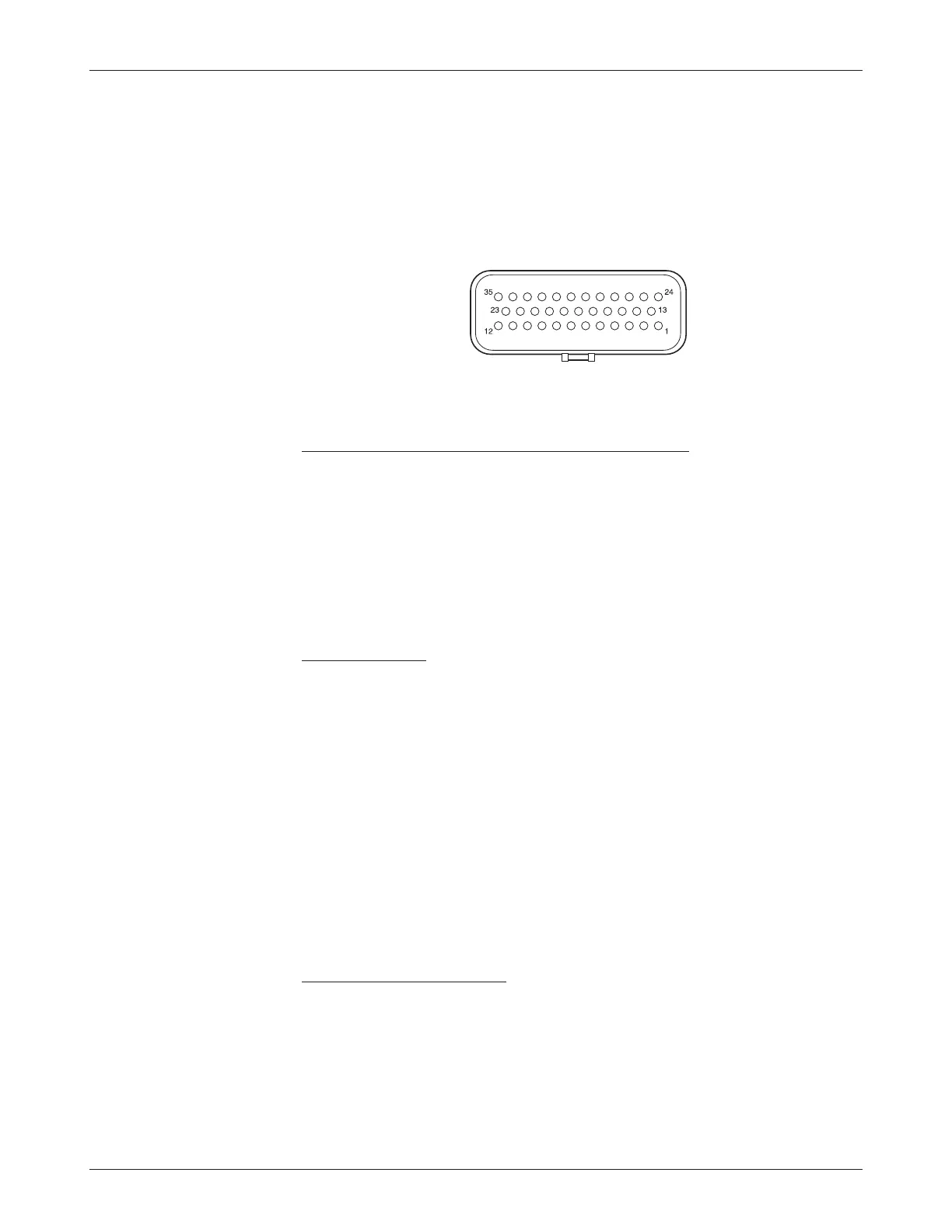
LOW CURRENT CONNECTIONS
All low power connections are made through a single 35-pin AMPSEAL con
-
nector. The mating plug housing is AMP p/n 776164-1 and the contact pins
are AMP p/n 770520-3. The connector will accept 20 to 16 AWG wire with
a 1.7 to 2.7mm diameter thin-wall insulation.
The 35 individual pins are characterized in Table 2.
2 — INSTALLATION & WIRING: Low Current Connections
J1
Low current wiring recommendations
Command input encoder and Steer motor encoder
The encoder wires should be bundled together as they run between the motor
and controller logic connector. These can often be run with the rest of the low
current wiring harness. The encoder cables should not be run near the motor
cables. In applications where this is necessary, shielded cable should be used
with the ground shield connected to the I/O ground (pin 18 or pin 30) at only
the controller side. In extreme applications, common mode filters (e.g. ferrite
beads) could be used.
CAN connection
The two CAN wires should be connected directly to the corresponding CAN
pins on the traction controller: running from pin 23 (CAN High) on the
steering controller to pin 23 (CAN High) on the traction controller, and from
pin 35 (CAN Low) on the steering controller to pin 35 (CAN Low) on the
traction controller.
Note: The 1222 controller has no internal 120
Ω CAN terminating
resistor. Typically the wiring of the CAN bus nodes is a daisy chain topology
with 120
Ω CAN terminating resistors at each end. If the vehicle wiring is done
such that the 1222 is the last node in the chain, an external 120
Ω terminating
resistor should be provided by the OEM in the wiring harness.
CAN wiring should be kept away from the high current cables and cross
it at right angles when necessary.
All other low current wiring
The remaining low current wiring should be run according to standard practices.
Running low current wiring next to the high current wiring should always be
avoided.