4
Curtis 1222 Manual, os 15
2 9 J A N U A R Y 2 0 1 3 D R A F T
2 — INSTALLATION & WIRING
2
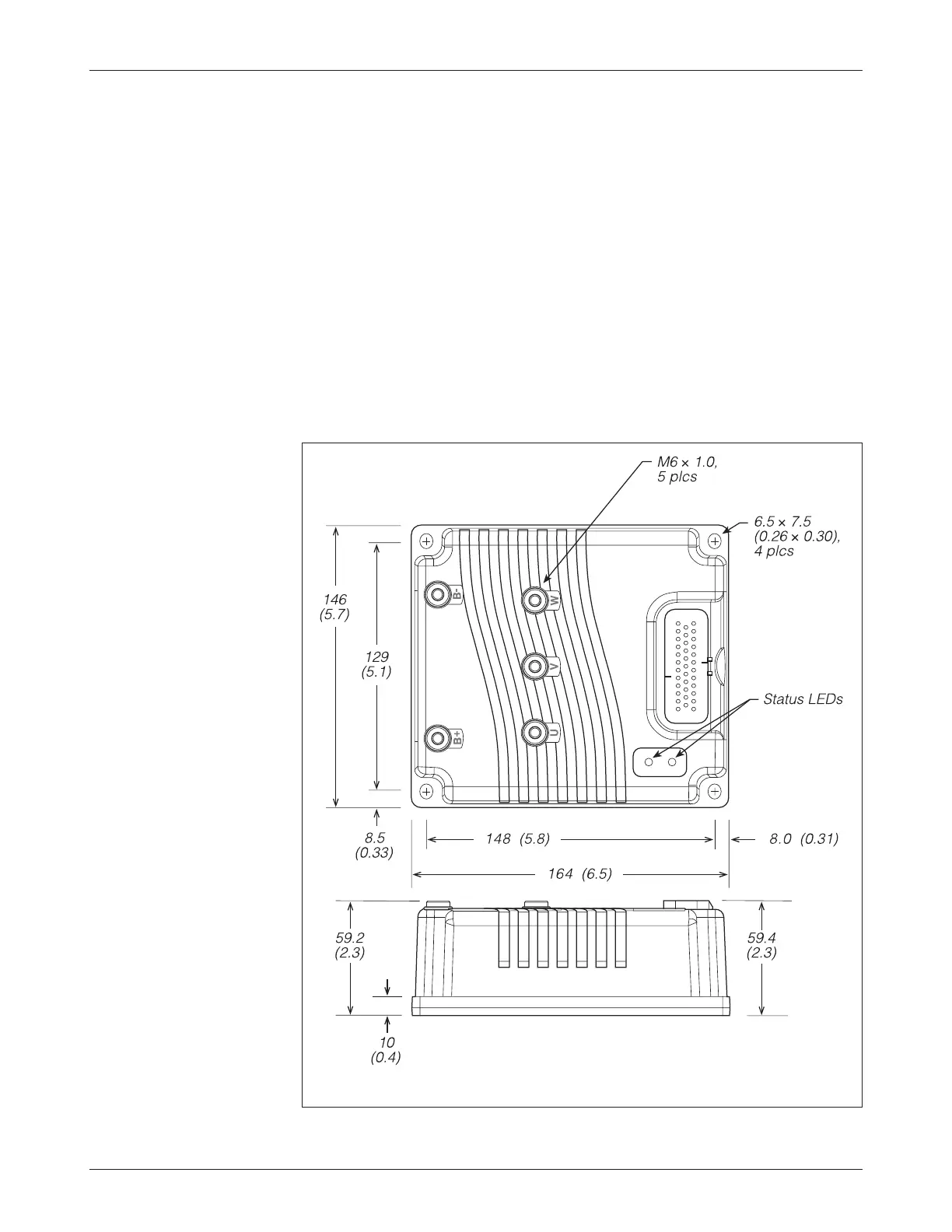
Fig. 2 Mounting
dimensions, Curtis 1222
motor controller.
Dimensions in millimeters (and inches)
INSTALLATION AND WIRING
MOUNTING THE CONTROLLER
The outline and mounting hole dimensions for the 1222 controller are shown
in Figure 2. The controller meets the IP65 requirements for environmental
protection against dust and water. Nevertheless, in order to prevent external
corrosion and leakage paths from developing, the mounting location should
be carefully chosen to keep the controller as clean and dry as possible.
It is recommended that the controller be fastened to a clean, flat metal
surface with four 6mm (1/4") diameter bolts, using the holes provided. A thermal
joint compound can be used to improve heat conduction from the controller
heatsink to the mounting surface. Additional heatsinking or fan cooling may
be necessary to meet the desired continuous ratings.