Curtis PMC 1297 Manual
11
Preliminary on Verso page is set with right edge at 7 and 7/8,
and the top (as on the Recto page) at 1/4.
Power Wiring
Traction motor armature wiring is straightforward, with the armature’s A1
connection going to the controller’s B+ bus bar and its A2 connection going to
the controller’s
TRACTION M- bus bar. The traction motor’s field connections are
less obvious. The direction of vehicle travel with the forward direction selected
will depend on how the motor’s field connections are made to the controller’s
two field terminals and how the motor shaft is connected to the drive wheels
through the vehicle’s drive train.
CAUTION:
The polarity of the F1 and F2
connections will affect the operation of the emergency reverse feature. The
forward and reverse switches and the field connections must be configured so
that the vehicle drives away from the operator when the emergency reverse
button is pressed.
The pump motor is wired as shown, with its S1 connection going to the
B+ bus bar and its A2 connection going to the PUMP M- bus bar.
Standard Control Wiring
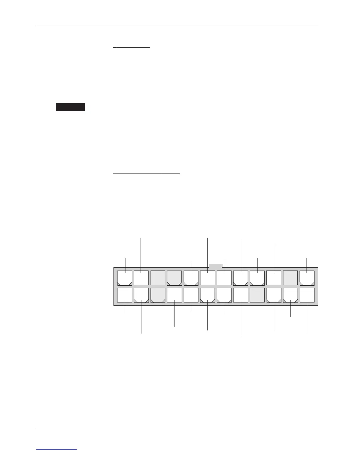
Wiring for the input switches and contactors is shown in Figure 4; the connector
is shown in more detail below.
The main contactor coil must be wired directly to the controller as shown in
Figure 4. The controller can be programmed to check for welded or missing
contactor faults and uses the main contactor coil driver output to remove power
from the controller and motors in the event of various other faults. If the main
contactor coil is not wired to J1 Pin 17, the controller will not be able to
open the main contactor in serious fault conditions and the system will
therefore not meet EEC safety requirements.
2 — INSTALLATION & WIRING: Controller
INTERLOCK
EMERGENCY
REVERSE
HORN
LIFT LIMIT
SWITCH
24-pin detail (see Fig. 4):
LOWERING
VALVE
DRIVER
LOAD HOLD
VALVE
DRIVER
MAIN
CONTACTOR
DRIVER
DISPLAY
GROUND
AUX
DRIVER
KEYSWITCH
INPUT (KSI)
EMERGENCY
REVERSE
CHECK
ELECTRO-
MAGNETIC
BRAKE
DRIVER
DISPLAY
POWER
LIFT
SWITCH
DISPLAY
D ATA
LOWER
SWITCH
COAST
SWITCH
HORN
DRIVER
MODE
SWITCH
(M1/M2)
24 23 22 21 20 19 18 17 16 15 14 13
121110987654321
☞
CAUTION