Curtis PMC 1297 Manual
28
slower the vehicle will creep down ramps. This creeping speed depends on the
restraint setting, the steepness of the ramp, and the vehicle load weight. The
restraint feature can never hold a vehicle perfectly stationary on a ramp and is
not intended to replace a mechanical or electromagnetic brake for this purpose.
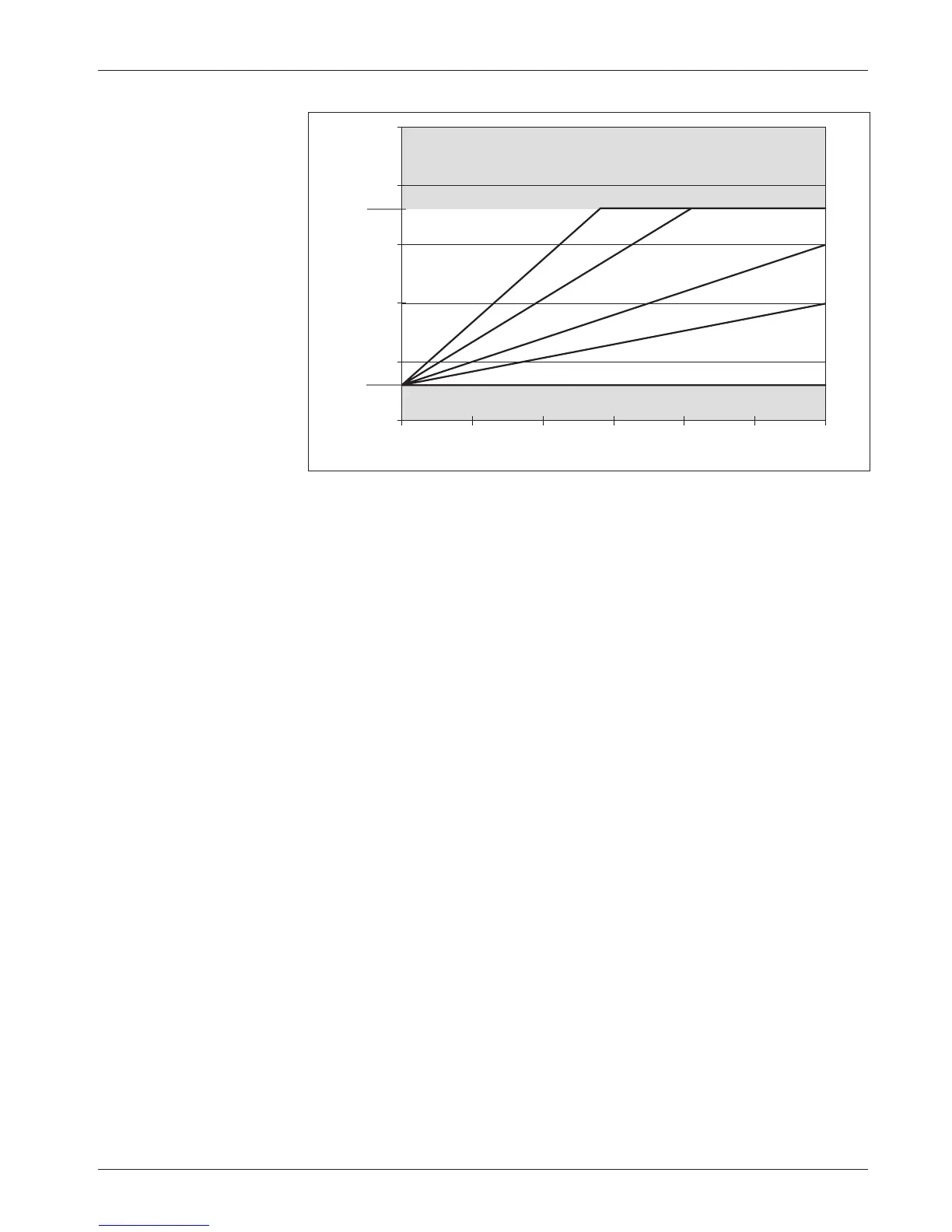
The restraint parameter establishes a mapping of field current to armature
current, as shown in Figure 12, and is adjustable from the programmed
minimum field (Field Min) to the full rated current. As shown in the diagram,
restraint is limited by the programmed maximum field (Field Max). Setting the
restraint parameter to a high value will cause strong braking, in an effort to
bring the vehicle speed down to the requested speed. Extremely high values may
cause the vehicle speed to oscillate (“hunt”) while in ramp restraint.
The restraint parameter is tuned as part of the vehicle performance
adjustment process (Section 5).
VARIABLE BRAKE
The variable braking parameter defines how the controller will apply braking
force when braking is requested. If the variable braking parameter is pro-
grammed On, the amount of braking current applied by the controller will be
a function of the throttle’s position when braking is requested. With variable
braking, the operator can use the throttle to control the amount of braking force
applied to a moving vehicle. Increasing throttle in the direction opposite to the
vehicle’s motion will apply increasing amounts of regenerative braking current
to the motor, slowing the vehicle more quickly.
If a fixed amount of braking force is preferred, the variable braking
parameter should be programmed Off. With variable braking Off, the control-
ler applies the full programmed braking current as soon as direction is reversed.
3
A
— PROGRAMMABLE TRACTION PARAMETERS: Braking
ARMATURE CURRENT (amps)
FIELD CURRENT (amps)
300250200150100500
25
20
15
10
5
0
Field Max
= 18 A
Field Min
= 3 A
Brake C/L
= 300 A
Restraint = 35 A
Restraint = 25 A
Restraint = 15 A
Restraint = 10 A
Restraint = 3 A
Fig. 12 Ramp restraint
map for controller with
Field Min set at 3 amps,
Field Max set at 18 amps,
and braking current limit
set at 300 amps.