Curtis PMC 1297 Manual
34
3
A
— PROGRAMMABLE TRACTION PARAMETERS: Throttle
Throttle Type 2 (0–5V, single-ended)
Throttle Type 1 (5kΩ–0)
5V
0
0.2V
40% Deadband
10% Deadband
0% Deadband
0.7V
2.1V
5V
0
3.3V
(5.0kΩ)
40% Deadband
10% Deadband
0% Deadband
3.0V
(4.5kΩ)
2.1V
(3.0kΩ)
0.2V
(0Ω)
0.2V
(0Ω)
0.2V
(0Ω)
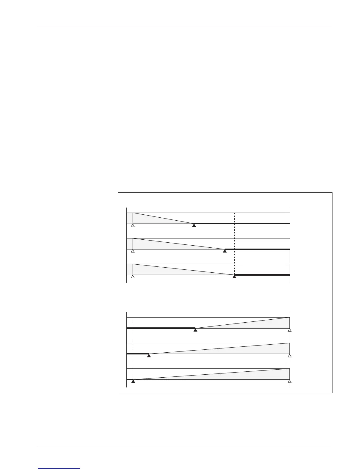
Fig. 13 Effect of adjusting
the throttle deadband
parameter
(throttle types 1 and 2).
THROTTLE DB
The throttle deadband parameter defines the throttle pot wiper voltage range
that the controller interprets as neutral. Increasing the throttle deadband setting
increases the neutral range. This parameter is especially useful with throttle
assemblies that do not reliably return to a well-defined neutral point, because it
allows the deadband to be defined wide enough to ensure that the controller goes
into neutral when the throttle mechanism is released.
Examples of deadband settings (0%, 10%, 40%) are shown in Figure 13
for the four throttle types (see Table 3). In all the examples in Figure 13, the
throttle max parameter is set at 100%.
The throttle deadband parameter is adjustable from 0% to 40% of the
nominal throttle wiper range; the default setting is 10%. The nominal throttle
wiper voltage range depends on the throttle type selected. See Table 1 (page 12)
for the characteristics of your selected throttle type.
The throttle deadband is tuned as part of the vehicle performance adjust-
ment process (Section 5).