Curtis PMC 1297 Manual
19
Preliminary on Verso page is set with right edge at 7 and 7/8,
and the top (as on the Recto page) at 1/4.
2 — INSTALLATION & WIRING: Emerg. Rev. Check & Spyglass
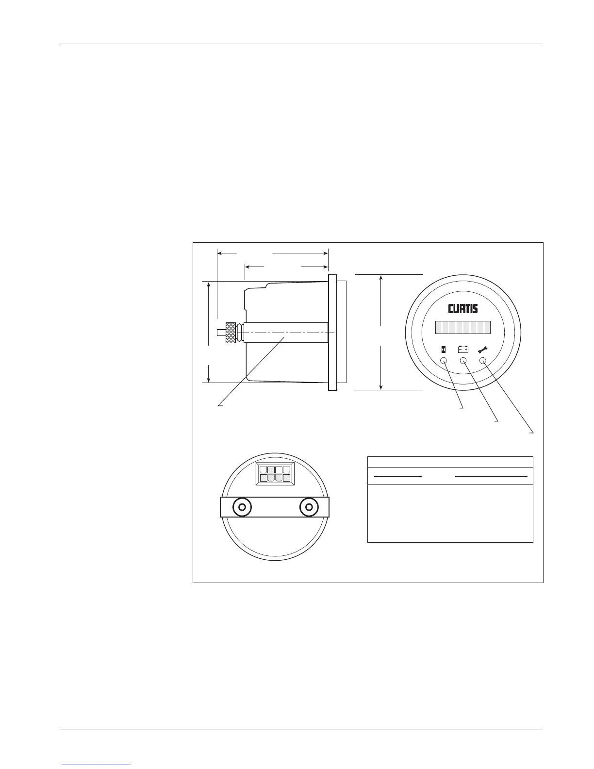
Fig. 11 Wiring guide and
mounting dimensions for
Curtis Spyglass display.
58
(2.25)
44 (1.75)
8
58 (2.25)
Service LED (red)
BDI LED (yellow)
Hourmeter LED (green)
52
(2.0)
“U” clamp for
up to 6 (0.25)
panel thickness
5
41
WIRING GUIDE
SPYGLASS 1297 CONTROLLER
PIN # FUNCTION J1 PIN # J2 PIN # J3 PIN #
1–4 N.C. –––
5 +12V, +15V 16 1 4
6 receive data 13 5 3
7 N.C. –––
8 ground (B+) 15 2 2
NOTE:
The Spyglass display can be connected to any
of the 1297’s low current connectors: J1, J2, or J3.
not connected, the vehicle will not operate. If the option is not selected and the
check wire is connected, no harm will occur—but continuity will not be
checked.
WIRING: Spyglass Display
The Curtis 840 Spyglass features an 8-character LCD display that sequences
between hourmeter, BDI, and fault messages. Three indicator LEDs—hourmeter,
BDI, and service—are also located on the face of the gauge.
The mating 8-pin connector is Molex 39-01-2085, with 39-00-0039
(18–24 AWG) pins.
Dimensions in millimeters (and inches)