Curtis PMC 1297 Manual
37
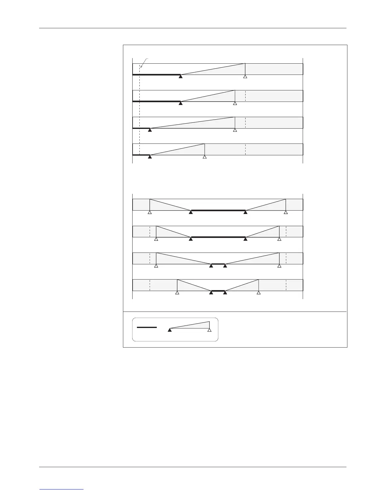
Fig. 14, cont’d
Effect of adjusting the
throttle max parameter
(throttle types 3 and 4).
Throttle Type 3 (0–5kΩ)
Throttle Type 4 (0–5V, wigwag)
0
5V
1.4V
(2.0kΩ)
3.3V
(5.0kΩ)
100% Throttle Max
40% Deadband
0.5V
(400Ω)
2.1V
(3.0 kΩ)
3.0V
(4.5kΩ)
90% Throttle Max
40% Deadband
90% Throttle Max
10% Deadband
60% Throttle Max
10% Deadband
Notes: Voltages shown are at the pot wiper relative to B-.
For throttle types 1 and 3, the deadband points are
defined in terms of the nominal 5kΩ pot resistance.
Using a pot of greater or lesser resistance will give
different values for the deadband points.
KEY
100%
Neutral
Deadband
Controller
Output
0%
1.4V
(2.0kΩ)
0.5V
(400Ω)
3.0V
(4.5kΩ)
0
5V
100% Throttle Max
40% Deadband
90% Throttle Max
40% Deadband
90% Throttle Max
10% Deadband
60% Throttle Max
10% Deadband
3.3V
4.5V
0.5V
1.7V
3.3V
4.3V
0.7V
1.7V
2.7V
4.3V
0.7V
2.3V
2.7V
3.7V
1.3V
2.3V
0.2V (0Ω)
3
A
— PROGRAMMABLE TRACTION PARAMETERS: Throttle