Curtis PMC 1297 Manual
39
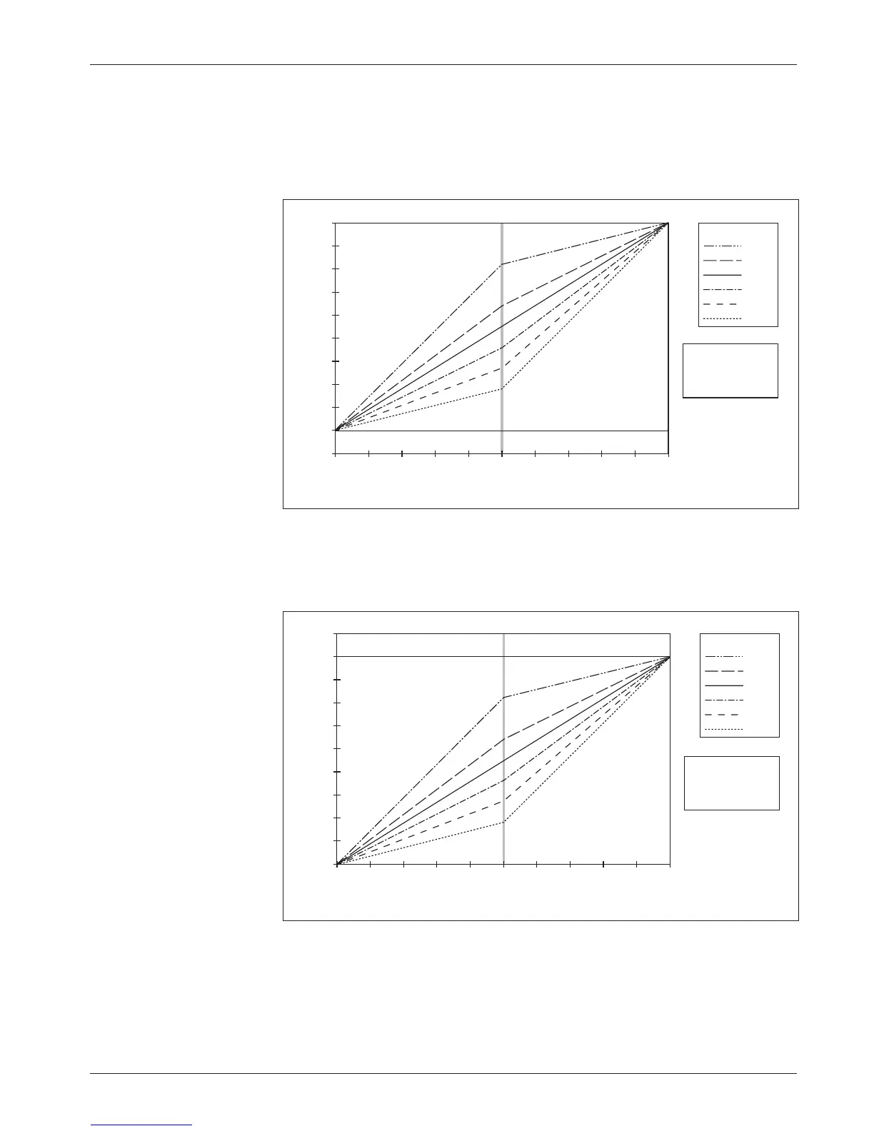
In Figure 16, the creep speed is increased to 10% and the maximum speed
is left at 100%, resulting in a controller output range of 90%. With these speed
settings, a 50% throttle map will result in 55% output (45% + 10%) at half
throttle.
Fig. 16 Throttle maps for
controller with maximum
speed set at 100% and
creep speed set at 10%.
Fig. 17 Throttle maps for
controller with maximum
speed set at 90% and
creep speed set at 0%.
In Figure 17, the maximum speed is decreased to 90% and the creep speed
is left at 0%; again, the controller output range is 90%. With these speed
settings, a 50% throttle map will result in 45% output at half throttle.
TRACTION THROTTLE INPUT (percent of active range)
80%
60%
50%
40%
30%
20%
THROTTLE MAP
100
90
80
70
60
50
40
30
20
10
0
100908070605040302010 0
SPEED PARAMETERS
10% Creep Speed
100% Max Speed
CONTROLLER OUTPUT (percent PWM)
TRACTION THROTTLE INPUT (percent of active range)
CONTROLLER OUTPUT (percent PWM)
80%
60%
50%
40%
30%
20%
THROTTLE MAP
100
90
80
70
60
50
40
30
20
10
0
100908070605040302010 0
SPEED PARAMETERS
0% Creep Speed
90% Max Speed
The throttle map operates within the window established by the Creep
Speed, Max Speed, Throttle Deadband, and Throttle Max parameters, as
shown in Figure 18. Creep Speed and Max Speed define the controller’s output
range, while Throttle Deadband and Throttle Max define the throttle’s active
3
A
— PROGRAMMABLE TRACTION PARAMETERS: Throttle