EZ-USB Development Kit User Guide, Doc. # 001-66390 Rev. *D 27
Advanced Development Board
3.9 I
2
C Expanders
U8 and U10 are Philips PCF8574 I/O expanders. They connect to the I
2
C bus SCL and SDA pins,
and provide eight GPIO pins. U8 provides eight output bits, connected to the 7-segment readout U9.
U10 provides eight input bits: four connect to push buttons S2–S5 and four are uncommitted.
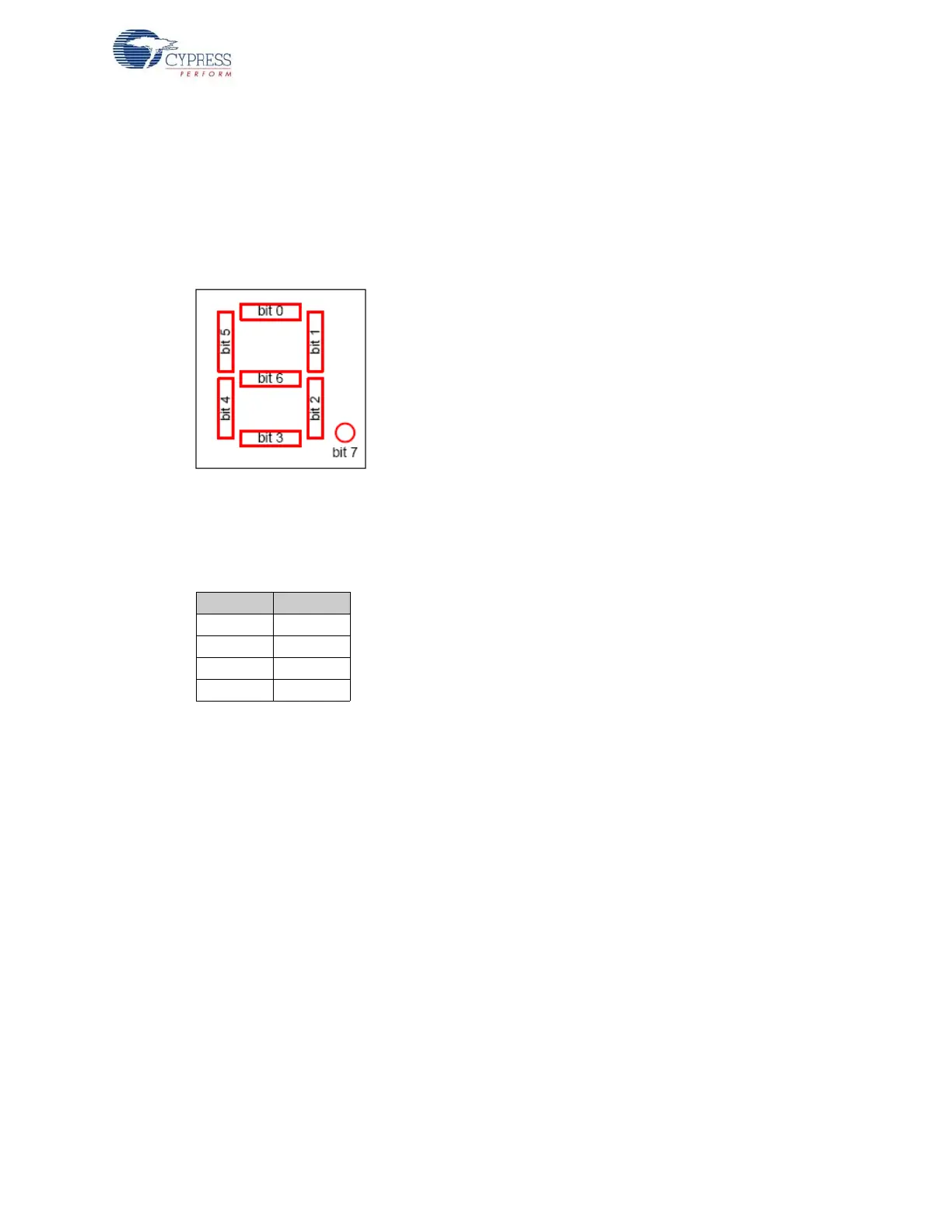
U8 connects to the 7-segment readout (U9) using the following bit assignments.
Figure 3-2. Bit Assignment
U8 has the group address 0100 and is strapped to the unit address 001. Therefore, to write a value
to the 7-segment readout, 8051 firmware sends a control byte of 01000010 (the least significant bit
(LSB0 indicates a write operation), followed by the data byte.
U10 uses its I/O pins as inputs, connected to S2-S5 according to the following table.
U9 has the group address 0100 and is strapped to unit address 000. Therefore, to read the switch
values, the 8051 firmware sends a control byte of 01000001 (the LSB indicates a read operation),
and then reads the data byte.
3.10 Indicators – Power and Breakpoint
LED D1 is connected to the PCB 5-V power supply, which is normally supplied from the USB cable
(VBUS pin). Alternatively, JP2 can be removed and an external 5-V power can be applied to the JP2
pin 1. In either case, D1 indicates the presence of the 5-V power.
LED D6 is connected to the 3.3-V voltage regulator output.
LED D7 is connected to the EZ-USB breakpoint (BKPT) pin. When using the Keil software develop-
ment tools, this green LED indicates that the EZ-USB development board has enumerated and the
Keil monitor has loaded and started running.
Bit Switch
0S2
1S3
2S4
3S5