28 EZ-USB Development Kit User Guide, Doc. # 001-66390 Rev. *D
Advanced Development Board
3.11 General-Purpose Indicators
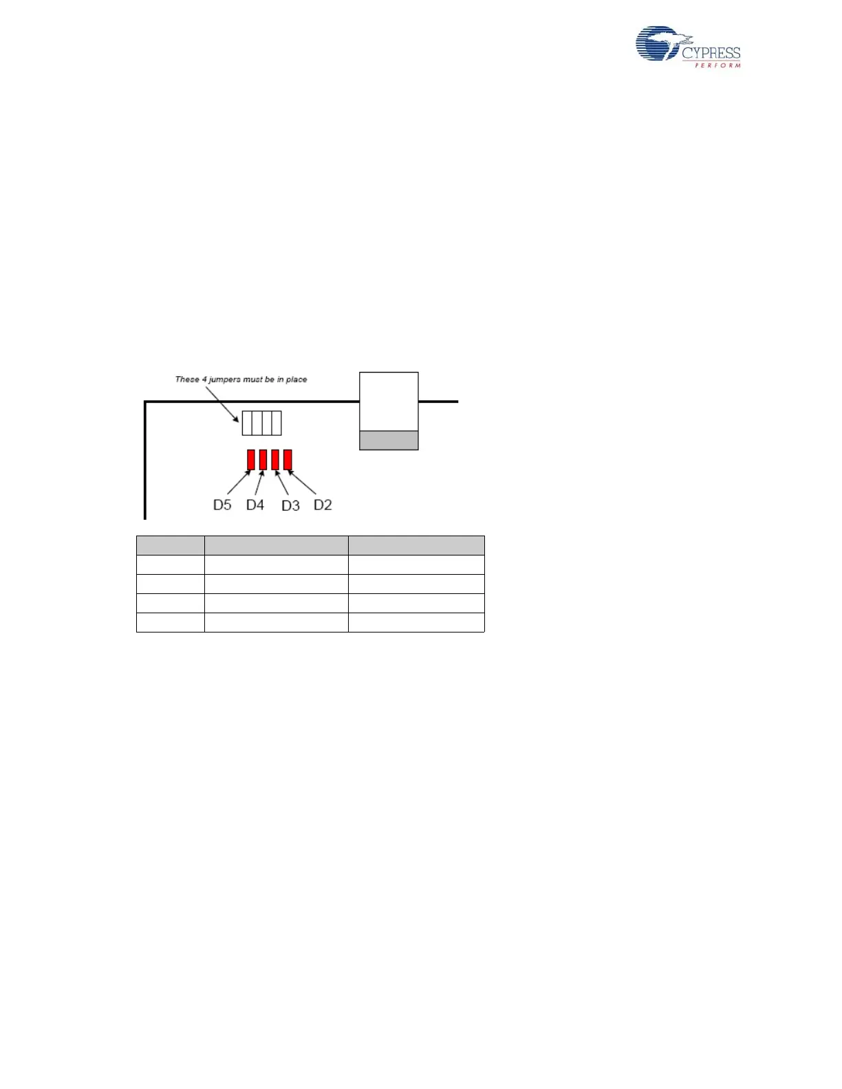
A portion of the GAL (U2) decodes 8051 reads to certain external memory addresses to turn the four
general-purpose indicators D2–D5 on and off. The following figure shows the positions of the four
indicator LEDs and a table of the external 8051 addresses, which are read to turn them on and off.
The four jumpers above the LEDS must be installed to use this feature. These jumpers connect the
LEDS to four GAL outputs.
Notes
■ The CLKOUT signal is used as a clock to latch the LED output signals from the GAL. If CLKOUT
is disabled, the LEDs will not update.
■ To use the LEDS for other purposes, such as wiring to other PC board signals for observation,
first remove the shorting plug to disconnect the LED from the GAL. The LED terminal is the bot-
tom pin of the connector and the GAL I/O pin is the top pin.
Figure 3-3. Indicator LED Positions
The low address byte is “don’t care”. This means you can efficiently add software test points using
the following code:
D5ON: mov MPAGE,#B8h ; turn D5 on
movx a,@r0 ; dummy read
;
D5OFF: mov MPAGE,#B0h ; turn D5 off
movx a,@r0 ; dummy read
This code example uses the 8051 8-bit indirect addressing mode. The MPAGE register (SFR 0x92)
supplies the high address byte and r0 supplies the low address byte. Register r0 does not require ini-
tialization because the low address byte is “don’t care” for the LED decoding.
To turn the LEDs ON and OFF using the C code, declare the external memory locations, and then
read their values into dummy variables:
xdata volatile unsigned char D5ON _at_ 0xB800;
xdata volatile unsigned char D5OFF _at_ 0xB000;
unsigned char dum;
dum = D5ON; // turn D5 on
dum = D5OFF; // turn D5 off
Note Program execution at these addresses do not activate the LEDs.
Indicator Turn ON by Reading Turn OFF by Reading
D2 0x88-- 0x80--
D3 0x98-- 0x90--
D4 0xA8-- 0xA0--
D5 0xB8-- 0xB0--