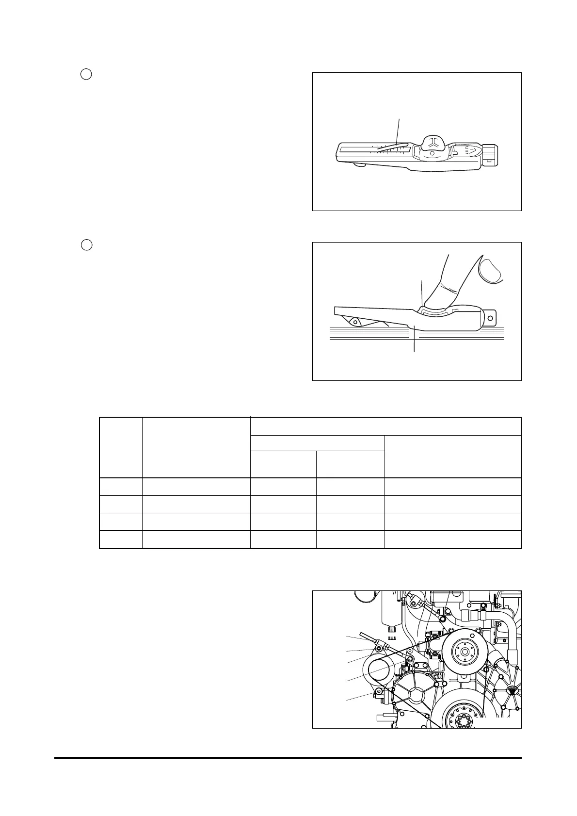
4) Measuring tension
Lower indicator arm (1) into the scale.
•
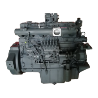
Apply tester to belt at a point midway
between two pulleys so that edge of
contact surface (2) is flush with the V-
belt.
•
Slowly depress pad (3) until the
spring can be heard to disengage.
This will cause the indicator to move
upwards. If pressure is maintained
after the spring has disengaged a
false reading will be obtained!
Reading of tension
•
Read of the tensioning force of the
belt at the point where the top sur-
face of the indicator arm (1) inter-
sects with the scale.
•
Before taking readings make ensure
that the indicator arm remains in its
position.
(5) Tensioning and changing V-belt
•
Remove fixing bolts. (1)
•
Remove lock nut. (2)
•
Adjust nut (3) until V-belts have cor-
rect tensions.
•
Retighten lock nut and fixing bolts.
To change the V-belts loosen mounting
bolts (1) and lock nut (2) and push ten-
sion pulley inwards by turning adjust-
ing nut (3).
- 173 -
MAINTENANCE OF MAJOR COMPONENTS
Tensioning forces on the tester
Type Drive belt width
new installation
When servicing after
Installation
After 10 min.
long running time
running time
M 9.5 mm 50 kg 45 kg 40 kg
A 11.8 mm 55 kg 50 kg 45 kg
B 15.5 mm 75 kg 70 kg 60 kg
C 20.2 mm 75 kg 70 kg 60 kg