Do you have a question about the Daikin DCM601B51 and is the answer not in the manual?
Verify that all included accessories for the intelligent Touch Manager are present as per the accessory list.
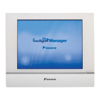
Review the detailed external dimensions of the intelligent Touch Manager body and mounting plate.
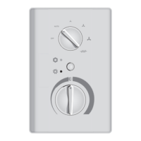
Identify the locations of terminals and switches on the rear, front, and side faces of the unit.
Select an appropriate installation location based on environmental conditions and required clearances.
Procedure to remove the terminal cover and power supply terminal cover from the rear face.
Connect DAIKIN DIII-NET compatible air conditioning devices to the intelligent Touch Manager.
Connect the intelligent Touch Manager to a PC network using a LAN cable for remote operation.
Connect the I/O module to the intelligent Touch Manager for controlling non-DAIKIN peripheral equipment.
Connect external devices for emergency stop or electric energy metering to the unit.
Connect DGE601A52 units to expand air conditioner control capabilities.
Connect the intelligent Touch Manager to an AC power supply following safety guidelines.
Install the intelligent Touch Manager using the wall mounting method with a metal plate.
Install the intelligent Touch Manager by embedding its rear portion into the wall.
Install the intelligent Touch Manager directly onto a control enclosure using fixing screws.
Enable the built-in battery to retain settings during power outages.
Turn on the intelligent Touch Manager and connected air conditioners to begin setup.
Configure the display language for the setup screens and unit interface.
Adjust regional settings like date, time, temperature, and decimal point format.
Configure the local standard time zone for the system clock.
Adjust the system clock and set up the daylight saving time schedule.
Verify that connected air conditioners have been successfully registered.
Manually assign unique DIII-NET addresses to each air conditioner for system identification.
Configure demand address and enable demand settings for outdoor unit functionality.
Set the Airnet address for the outdoor unit to enable Energy Navigator function.
Understand the LED and segment display indications for various outdoor unit settings.
Display information of areas and management points in a list format for quick overview.
Navigate and view areas and management points in a hierarchical structure.
Initiate or terminate the operation of specific areas or management points.
| Model | DCM601B51 |
|---|---|
| Category | Controller |
| Compatibility | Daikin VRV systems |
| Display | LCD |
| Functions | Temperature control, scheduling |