Installation Manual 3P291714-7H
DCM601B51 intelligent Touch Manager
31English
3.3 Direct mounting to control enclosure
3.3.1 Parts to be used
To mount the intelligent Touch Manager directly to the control enclosure, use the following
accessory mounting parts:
• Pan-head screw (M4×40, with spring washer and plain washer), 4 pcs.
• Nut (φ4), 4 pcs.
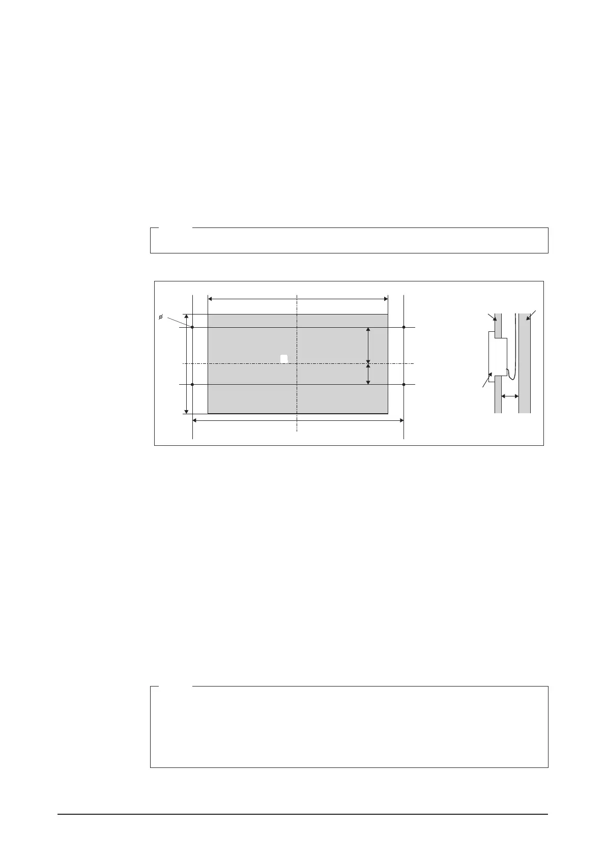
3.3.2 Wall opening dimensions
Use the following dimensional drawing to provide a sufcient opening.
NOTE
The supplied paper template helps you mark the dimensions of the required wall opening.
<Wall opening dimensions for direct mounting to control enclosure>
257mm
207mm
272mm
60mm
92mm
4
D
A
B
C
EE
A Control enclosure face plate
B Control enclosure inner wall
C intelligent Touch Manager
D 25mm min.
E Opening
3.3.3 Installation procedure
1. Remove the resin frame from the front face of the intelligent Touch Manager. This
frame is snapped into the edge of the monitor display. You can remove it by hand as
this is not screwed.
Removing the frame reveals four screw holes, two holes each to the left and right of the
monitor display.
2. Insert the intelligent Touch Manager into the opening of the control enclosure and
install it to the control enclosure using the pan-head screws.
NOTE
• When securing the intelligent Touch Manager in the control enclosure, do not over
tighten.
• After tightening the pan-head screws, make sure that the monitor switch still gives off
a tactile click when pushed.
Tightening torque value: 1.0N∙m
3. Snap the resin frame back into the front face of the intelligent Touch Manager as it was
before.