Installation Manual 3P291714-7H
DCM601B51 intelligent Touch Manager
19English
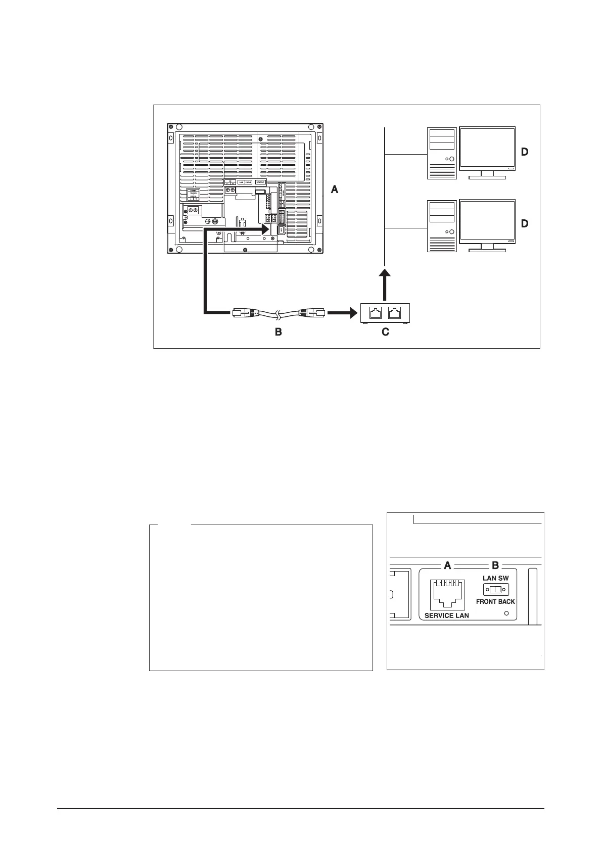
2.3.1 Terminals location and conceptual connection diagram
Using a LAN cable, connect the LAN socket to the network hub.
<Conceptual drawing of LAN connection>
A Rear face of intelligent Touch Manager
B LAN cable
C Hub
D PC
2.3.2 Requirements that must be met
• Applicable cable standard: 100Base-TX or 10Base-T
• Connector standard: RJ-45
<SERVICE LAN socket and LAN SW
switch>
NOTE
• If you are connecting to a LAN temporarily
during installation or maintenance, use the
SERVICE LAN terminal located on the front
face.
Changing the position of the LAN SW switch
to “FRONT” causes the SERVICE LAN socket
to activate (enabled for use).
• You cannot close the front switch cover when
the switch set to “FRONT”. To close the front
switch cover, select “BACK”.
A SERVICE LAN
B LAN SW