32 Installation Manual 3P291714-7H
DCM601B51 intelligent Touch Manager
English
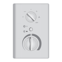
<Installing intelligent Touch Manager body to control enclosure>
MONITOR
A
A
A
A
B
B
B
B
A Pan-head screw
B Nut
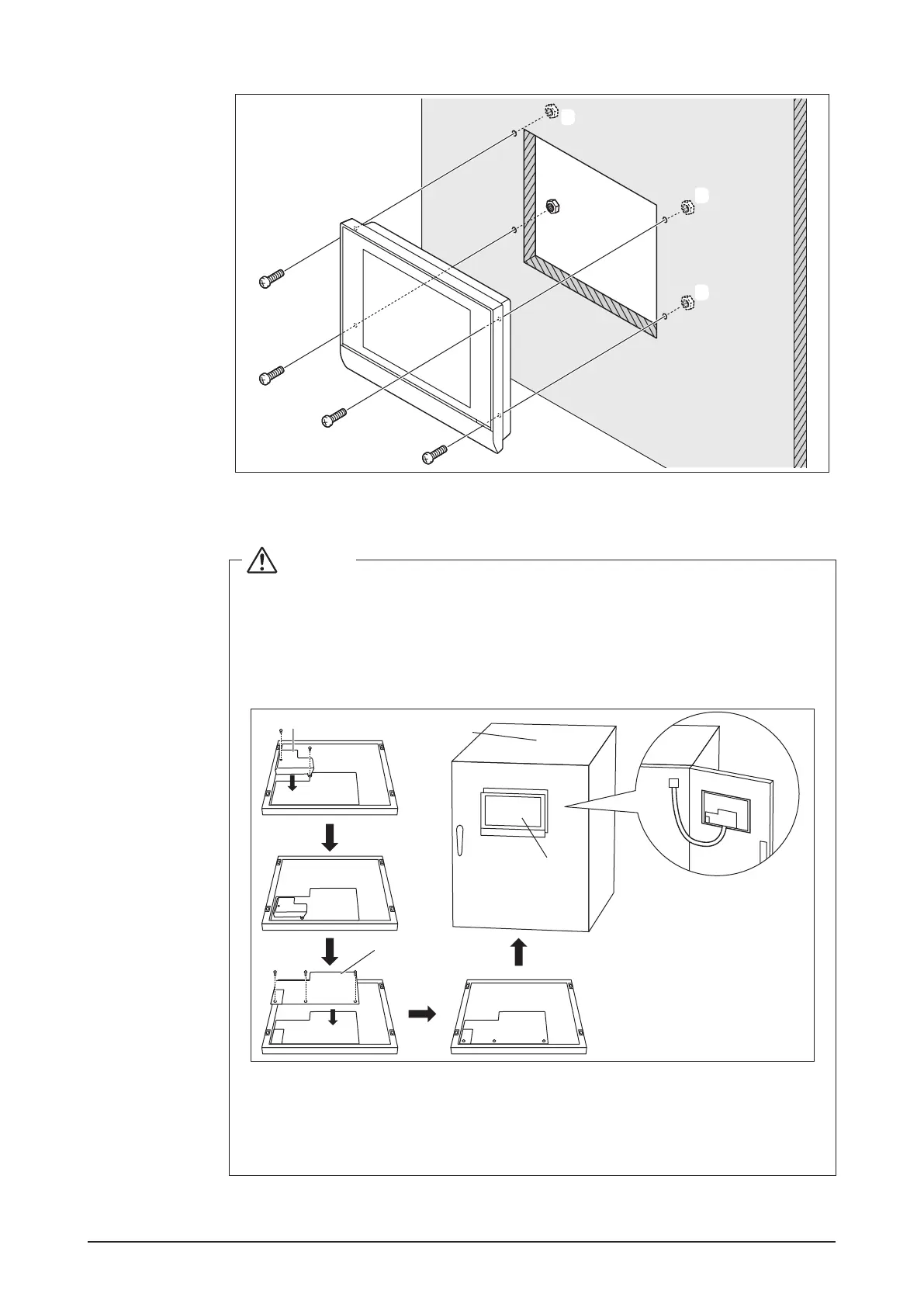
CAUTION
If the intelligent Touch Manager is directly mounted to the control enclosure, you
will be exposed to the power line connection terminals when opening the control
enclosure door.
To prevent the risk of an electric shock by accidentally touching these power
terminals, for safety, be sure to attach the power supply terminal cover and termi-
nal cover before starting the installation procedure.
A
B
C
D
A Power supply terminal cover
B Terminal cover
C Control enclosure
D intelligent Touch Manager