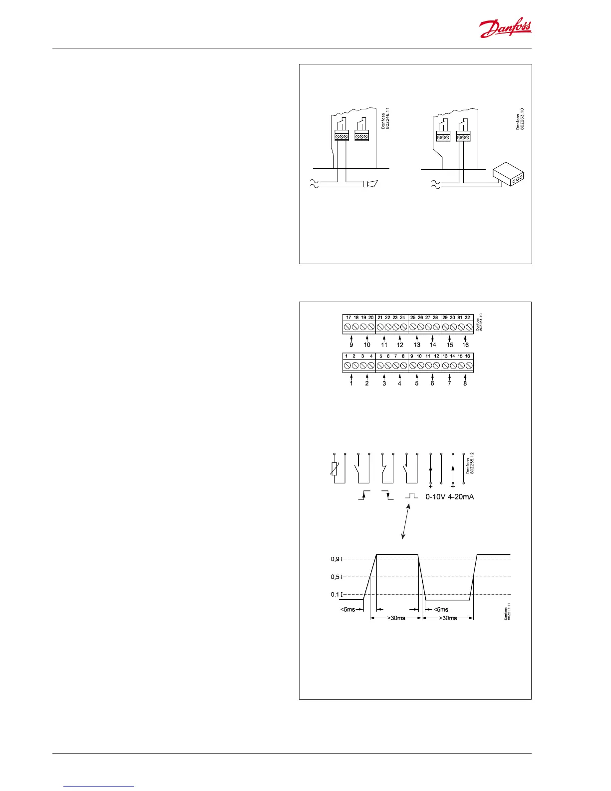
3. Direct measuring points
There are 16 direct measuring points.
All the odd numbers are signal inputs. All the even numbers
are earth. All the even numbers on the PCB behind the terminal
block are linked to a common earth.
If you use a common earth wire to several measuring points you
should delimit it into groups. Do not put temperature signals,
switch signals and voltage signals in the same group.
Keep your distance from sources of electrical interference and
power lines.
Sensor connections
One of the conductors is wired to an odd terminal block
number. The other is wired to earth (even number).
On/off signals from a switch function
One of the conductors is wired to an odd terminal block
number. The other is linked to earth (even number).
The switch can either be a make contact or a circuit breaker. The
function is defined under setup.
Output reading (pulse recording)
Only measuring points 1 and 2 can be used for output readings.
These inputs are designed for fast on/off changes.
Pulses are measured in accordance with DIN 43864.
The signal is wired as an on/off signal.
Voltage signal
The voltage can vary between 0 and 10 V DC.
Minus is wired to earth (even number).
Current signal
The current signal can vary between 4 and 20 mA.
Minus is wired to earth (even number).
DIN 43864
S01 interface
2. Relays
The two relays can be used for:
• External alarm function
When connected as shown, an alarm will be emitted in alarm
situations and when the power to the AK-SM 350 disappears.
• Resetting the supply voltage for a modem
After a power outage, the AK-SM 350 will control the supply
voltage for the modem, ensuring the modem restarts in a
controlled manner.
• Watchdog
Here the relay is enabled in time intervals. For example, once
an hour. If there is no relay change, an external unit will sound
an alarm.
The two relays must be connected to either low or high voltage
(115/230 V), but not low voltage on one and high voltage (115/230
V) on the other.
Relay 1
Relay 2
 Loading...